Method and device for producing masks for a laser installation

a laser installation and laser technology, applied in the field of laser installation mask production, can solve the problems of high wear, difficult to meet the needs of users, and inability to withstand stress for a long time, and achieve the effects of high brilliance, high colour intensity, and high colour intensity

Inactive Publication Date: 2012-09-20
AZACORP +1
View PDF20 Cites 23 Cited by
  • Summary
  • Abstract
  • Description
  • Claims
  • Application Information

AI Technical Summary

Benefits of technology

[0007]Consequently, it is a first object of the invention to provide a method and a device for producing masks and diaphragms that are highly wear-resistant, dimensionally stable, and suitable for use in laser installations for the creation of microstructures. This object is attained by the method wherein the areas which scatter the laser radiation are roughened and modified by irradiation with a femtosecond, picosecond, or fluor laser beam.

Problems solved by technology

Consequently, when irradiated with a high-energy laser, it is subject to high stresses that may lead to deformations and to high wear.
For the first possibility, a lacquer coat may be applied in these areas, but it will not withstand the stress for long.
However, this technique is very demanding.
For producing scattering areas, etching techniques are known in the art today, but these are far too inaccurate.
The above-mentioned disadvantages apply especially if masks serve for creating e.g. optically effective diffraction gratings and similar microstructures.
This severe drawback of a relatively coarse forming of areas with less transparency applies also to the roughening of surfaces according to JP 2002-011589 A which are produced by sandblasting.

Method used


Image

  • Method and device for producing masks for a laser installation
  • Method and device for producing masks for a laser installation
  • Method and device for producing masks for a laser installation

Examples


Embodiment Construction

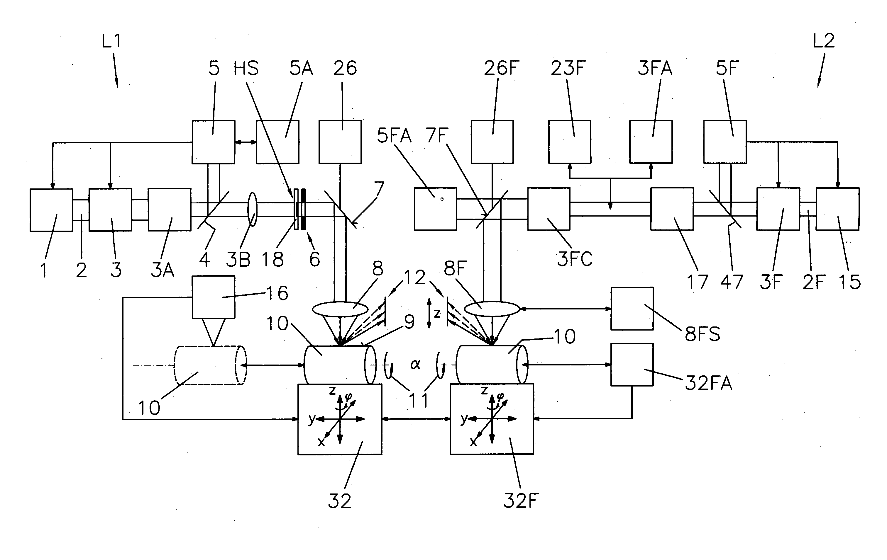
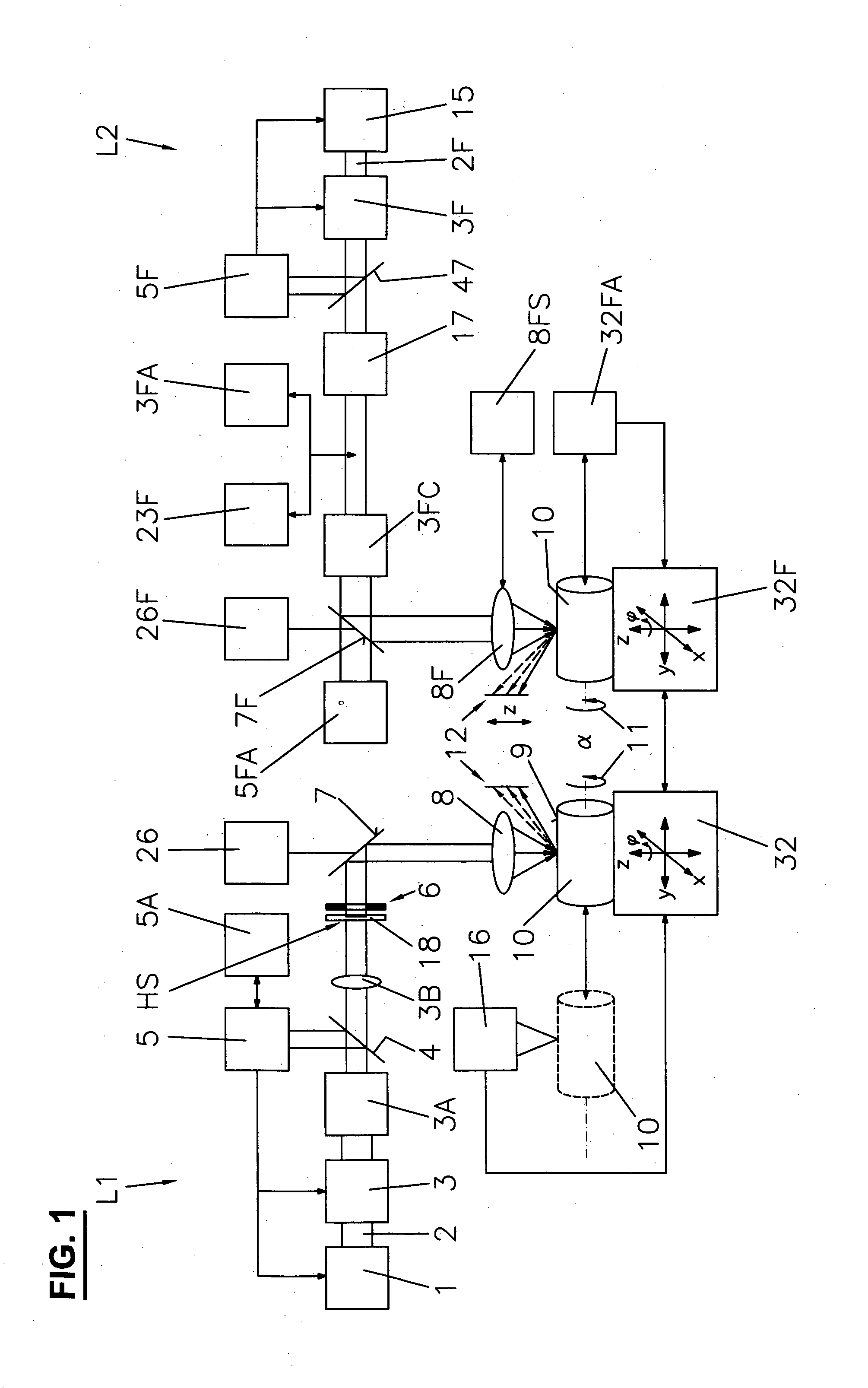
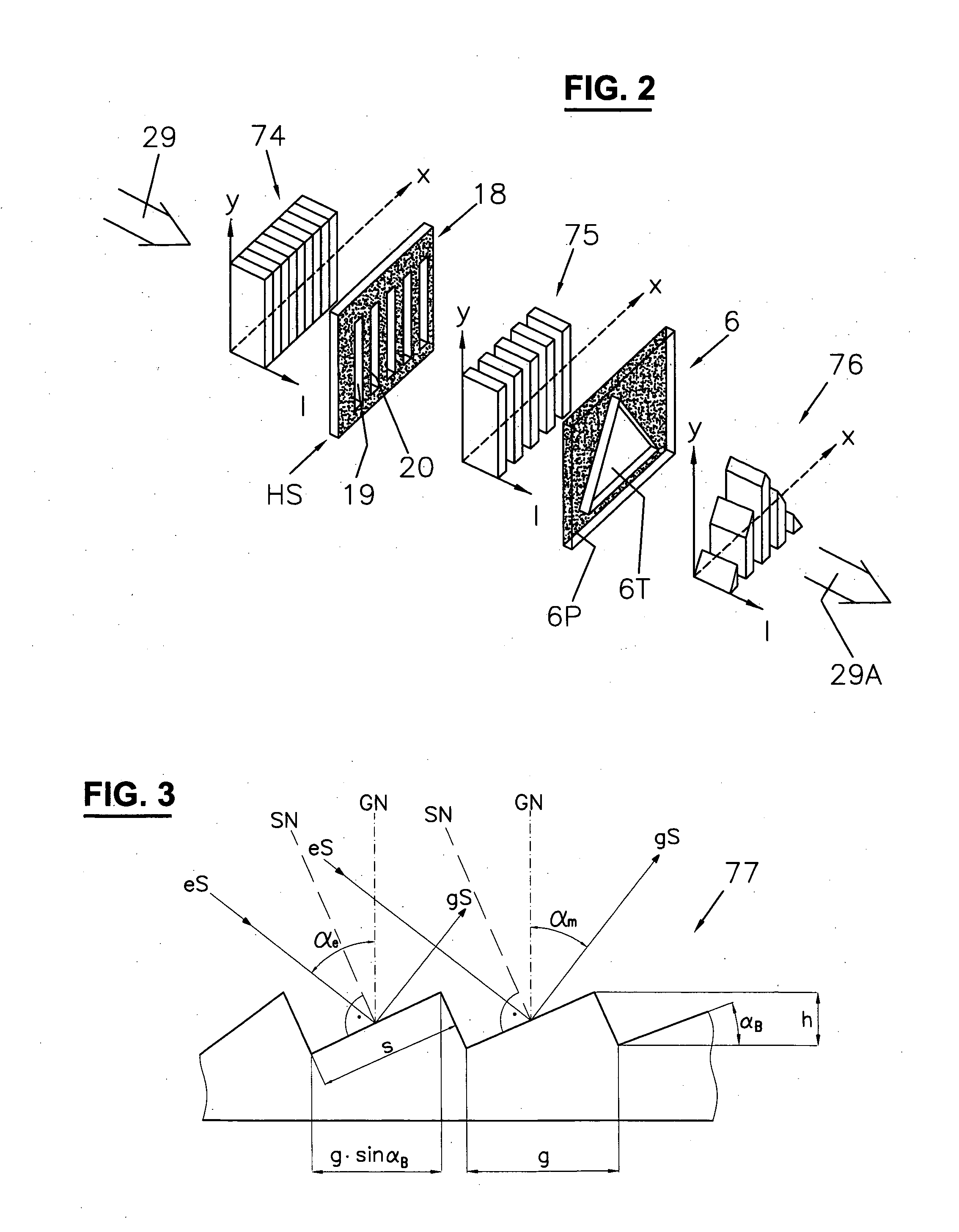
[0018]In FIG. 1, a device for producing diffraction gratings with two laser installations is illustrated of which the one on the left in the drawing is an excimer laser installation that is suitable for producing e.g. blazed grating arrays and the laser installation on the right is a femto- or picosecond laser installation that serves for creating masks and / or diaphragms for producing the grating structures, on one hand, and on the other hand is apt either to produce directly acting ripple grating structures or to superpose the grating structures produced by the excimer laser with a second grating structure that is based on a variation of the spacing between the ripples.

[0019]The first laser installation L1, comprising a KrF excimer laser having a wavelength of 248 nanometers nm, serves to produce microstructures in the solid body surface according to the mask projection technique, and the second laser installation L2, comprising a femtosecond laser 15 having a centre wavelength of ...


PUM

PropertyMeasurementUnit
wavelengthaaaaaaaaaa
grating periodsaaaaaaaaaa

Abstract

In the method for producing masks and / or diaphragms for a laser installation for the creation of microstructures on a solid body surface according to the mask projection technique, predetermined opaque surface portions which scatter the laser radiation are produced in the mask and / or diaphragm substrate by roughening and modifying the latter by means of a femtosecond, picosecond or fluor laser beam. Such masks and diaphragms have a strongly improved lifetime and accuracy and may e.g. serve for the creation of blazed gratings which, arranged in diffraction grating arrays on a solid body surface, serve for producing spectral colors and mixed colors of high brilliance.

Description

CROSS-REFERENCE TO RELATED APPLICATIONS[0001]This application is the National Phase of PCT / CH2010 / 000295, filed Nov. 22, 2010, which claims priority to European Application No. 09405228.9, filed Dec. 18, 2009. The contents of the foregoing applications are incorporated by reference in their entirety.FIELD OF INVENTION[0002]The present invention relates to a method for producing masks and / or diaphragms for a laser installation for the creation of microstructures on a solid body surface in which the areas of the masks and / or diaphragms that are opaque to the laser radiation scatter the incident laser radiation. For the sake of simplicity, only masks will be mentioned hereinafter, but this term also comprise diaphragms here.BACKGROUND OF THE INVENTION[0003]In certain laser installations, microstructures are created according to the mask projection technique, as e.g. disclosed in WO 2007 / 012215 to the applicant of the present invention. The laser may e.g. be a KrF excimer laser having a...

Claims


Application Information

Patent Timeline
Patent Type & Authority Applications(United States)
IPC IPC(8): B29C59/16B32B3/30G03F1/00G03F1/54
CPCB23K26/0039B23K26/0078B23K26/0635B23K26/0656Y10T428/24479B82Y40/00G03F1/14G03F1/54G03F7/0002B82Y10/00B23K26/0006B23K26/0624B23K26/066B23K26/3584B23K2103/50G03F1/00
Inventor BOEGLI, CHARLESWEISSMANTEL, STEFFENREISSE, GUNTERENGEL, ANDYBOETTCHER, RENESTEFFEN, WERNER
Owner AZACORP
Why Eureka
Try Eureka