In-wheel motor drive device

a technology of in-wheel motors and drives, which is applied in the direction of electric propulsion mounting, gearing details, gearing, etc., can solve the problems of reducing durability performance, difficult to control the assembly accuracy of casings and internal gears, etc., and achieves improved durability performance and assembly efficiency of in-wheel motor drives. , the effect of preventing uneven wear

Inactive Publication Date: 2012-09-27
NTN CORP
View PDF1 Cites 18 Cited by
  • Summary
  • Abstract
  • Description
  • Claims
  • Application Information

AI Technical Summary

Benefits of technology

[0019]As described above, the present invention has the cylindrical casing-side member that extends from the one axial end to the other axial end of the speed reduction portion and that has both one end and the other end formed integrally, and the both ends of the casing-side member rotatably support the output shaft. Thus, the output shaft can be supported at both ends, and can be held coaxially with the speed reduction portion. This can prevent the output shaft of the speed reduction portion from becoming non-parallel with the axis, against a radial load and a bending moment load which are applied from the wheel hub to the output shaft, and thus can prevent uneven wear in the speed reduction portion. As a result, durability performance of the in-wheel motor drive device is improved.
[0020]Moreover, the present invention has the output-shaft bearings and the input-shaft bearings at both axial ends of the speed reduction portion. This allows the components of the speed reduction portion, namely the casing-side member, the output shaft, the input shaft, and various rotating elements placed between the output shaft and the input shaft, to be produced as a unit. Thus, the speed reduction portion as a unit can be assembled on a separate assembly line from that of the in-wheel motor drive device, whereby assembly efficiency of the in-wheel motor drive device is improved.

Problems solved by technology

Thus, it is difficult to control assembly accuracy of the casings and the internal gear.
However, even slight displacement of the casings and the internal gear from the parallel arrangement after assembly is finished causes uneven wear of outer pins provided inside, thereby degrading durability performance.

Method used


Image

  • In-wheel motor drive device
  • In-wheel motor drive device
  • In-wheel motor drive device

Examples


Embodiment Construction

[0023]An embodiment of the present invention will be described in detail below with reference to the accompanying drawings.

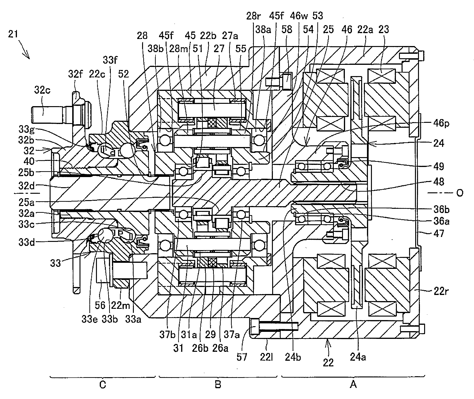
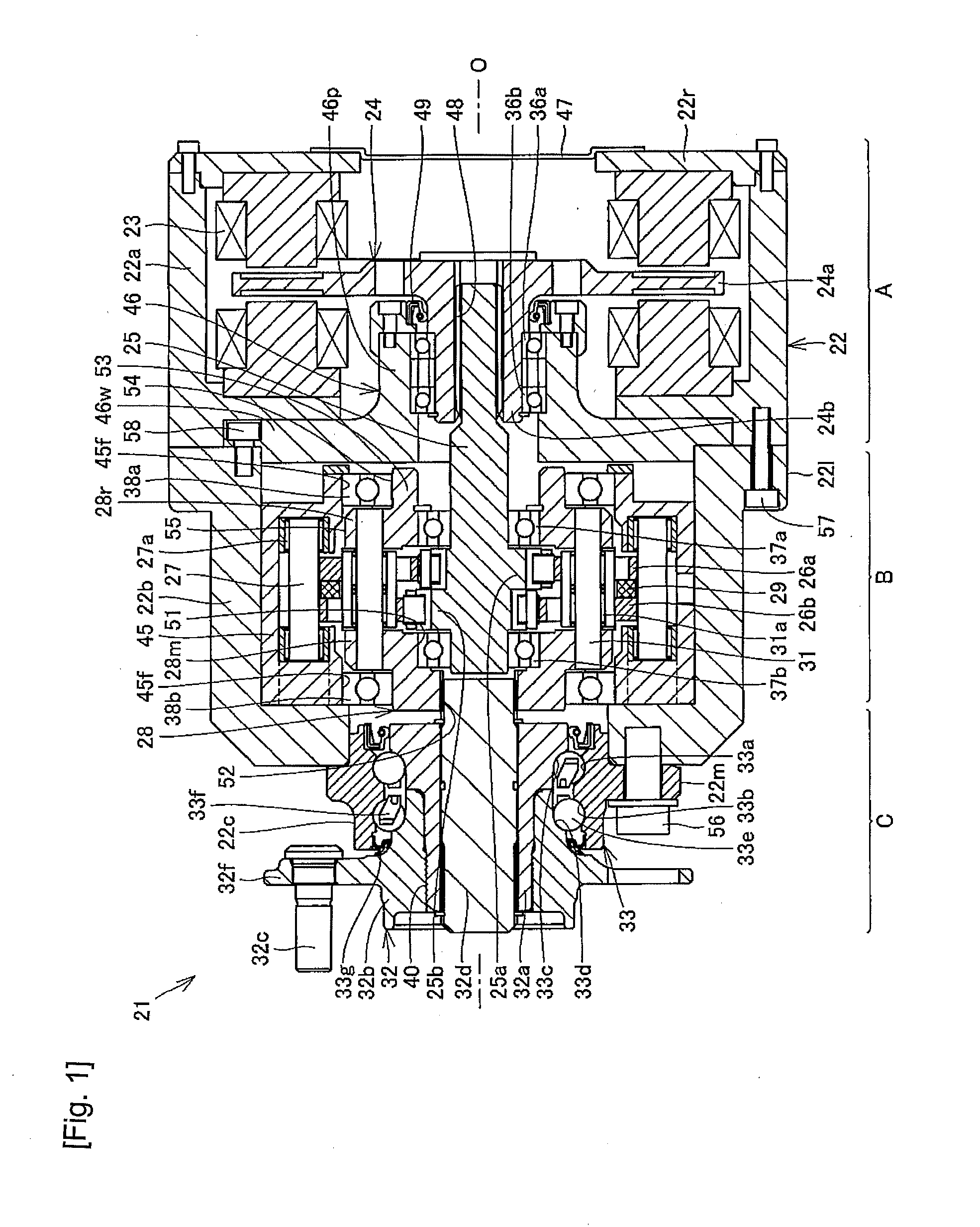
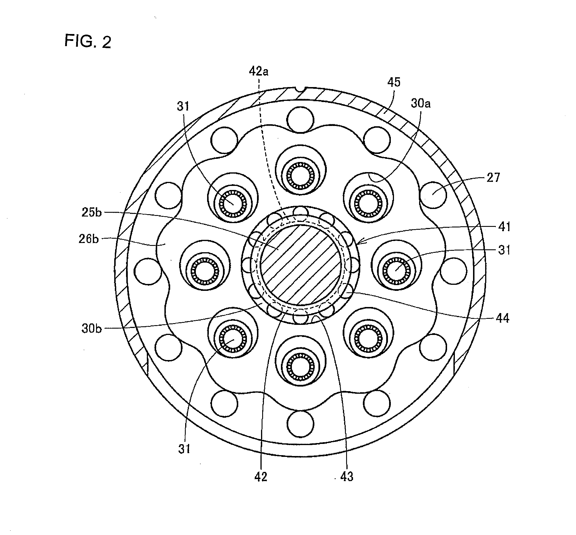
[0024]FIG. 1 is a longitudinal cross-sectional view showing an in-wheel motor drive device according to an embodiment of the present invention. FIG. 2 is a transverse cross-sectional view of a speed reduction portion in FIG. 1. An in-wheel motor drive device 21 includes a motor portion A as a motor drive device that generates a driving force, a speed reduction portion B that reduces the speed of rotation of the motor portion A to output the rotation having the reduced speed, and a wheel-hub bearing portion C that transmits the output of the speed reduction portion B to a driving wheel, not shown. The in-wheel motor drive device 21 is attached to a position inside a wheel housing of an electric car. The motor portion A, the speed reduction portion B, and the wheel-hub bearing portion C are sequentially arranged coaxially and in series in this order.

[0025]The moto...


PUM


Abstract

An in-wheel motor drive device 21 includes: a motor portion A; a speed reduction portion B that reduces the speed of rotation of the motor portion A to output the rotation having the reduced speed to an output shaft 28; and a wheel hub 32 coupled to the output shaft 28. The speed reduction portion B has a cylindrical casing-side member 45 that extends from one axial end to the other axial end of the speed reduction portion and that has both one end and the other end formed integrally, the output shaft 28 that is inserted through an inner space region of the casing-side member, and two output-shaft bearings 38a, 38b that are respectively provided on an inner periphery at both ends 45f of the casing-side member to rotatably support the output shaft 28.

Description

TECHNICAL FIELD [0001]The present invention relates to a support structure of an output shaft of an in-wheel motor drive device.BACKGROUND ART [0002]A structure as described in Japanese Patent No. 2,888,673 (Patent Literature 1) is known as a conventional cycloidal speed reduction mechanism. The structure described in Patent Literature 1 is a cycloidal speed reduction mechanism, and can achieve a high reduction ratio as compared to planetary gear speed reduction mechanisms as typical conventional speed reducers. However, in such a conventional cycloidal speed reduction mechanism, a casing that rotatably supports an output shaft at one end in an axial direction, an internal gear that is placed in a central portion in the axial direction, and a casing that rotatably supports the output shaft at the other end in the axial direction are coupled and fixed together by bolts extending parallel to an axis. Thus, it is difficult to control assembly accuracy of the casings and the internal ge...

Claims


Application Information

Patent Timeline
Patent Type & Authority Applications(United States)
IPC IPC(8): B60K7/00F16H1/32F16H57/021H02K7/116
CPCB60K7/0007B60K17/046B60K2007/0038Y02T10/641F16H1/32H02K7/116B60K2007/0092Y02T10/64
Inventor SUZUKI, MINORU
Owner NTN CORP
Why Eureka
Try Eureka