
Abnormality detecting system for battery assembly

a technology of abnormality detection and battery assembly, which is applied in the direction of electrochemical generators, electric devices, instruments, etc., can solve the problems of increasing the size of the system, affecting the detection efficiency of battery assemblies, so as to reduce or eliminate the possibility

Inactive Publication Date: 2012-09-27
TOYOTA JIDOSHA KK
View PDF10 Cites 20 Cited by
  • Summary
  • Abstract
  • Description
  • Claims
  • Application Information

AI Technical Summary

Benefits of technology

[0011]The invention provides an abnormality detecting system that is simply constructed to have a voltage monitoring function for each battery cell of a battery assembly, which is implemented by obtaining the result of comparison between a voltage value of each battery cell and a predetermined criteria voltage, without directly detecting the voltage value, thus making it less likely or unlikely to erroneously detect an abnormality (excessive increase) in the internal resistance.
[0016]The abnormality detecting system according to the above aspect of the invention is simply constructed to obtain the result of comparison between a voltage value of each battery cell and a predetermined criteria voltage, without directly detecting the voltage value, so as to reduce or eliminate the possibility of erroneously detecting an abnormality (excessive increase) in the internal resistance.

Problems solved by technology

However, if the abnormality detecting system is arranged to be able to output a voltage detection value for each battery cell, the number of sensors installed in the system and the number of signals handled by the system are increased, which may result in a complicated arrangement or construction of the abnormality detecting system, and an increased size of the system.
Thus, if the abnormality detecting system is simply constructed as described above, it may be difficult to detect voltage values and current values while bringing them precisely into synchronization with each other.
In this case, an abnormality (excessive increase) in the internal resistance may be erroneously detected, because of an error in current detection due to loss of synchronism.

Method used


Image

  • Abnormality detecting system for battery assembly
  • Abnormality detecting system for battery assembly
  • Abnormality detecting system for battery assembly

Examples


Embodiment Construction

[0028]One embodiment of the invention will be described in detail with reference to the drawings. In the following, the same reference numerals are assigned to the same or corresponding portions or elements in the drawings, and the explanation of these portions or elements will not be repeated.

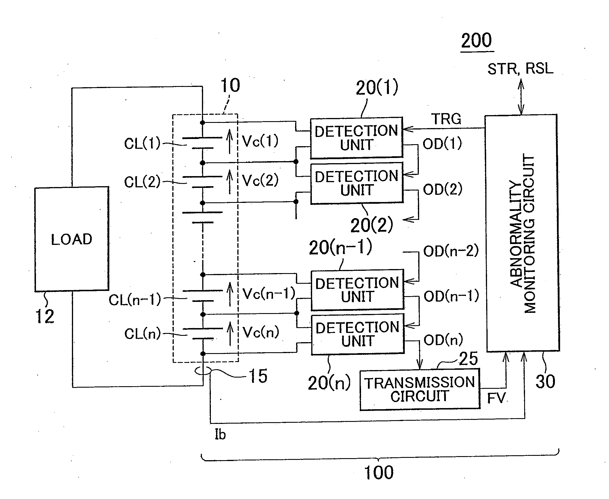
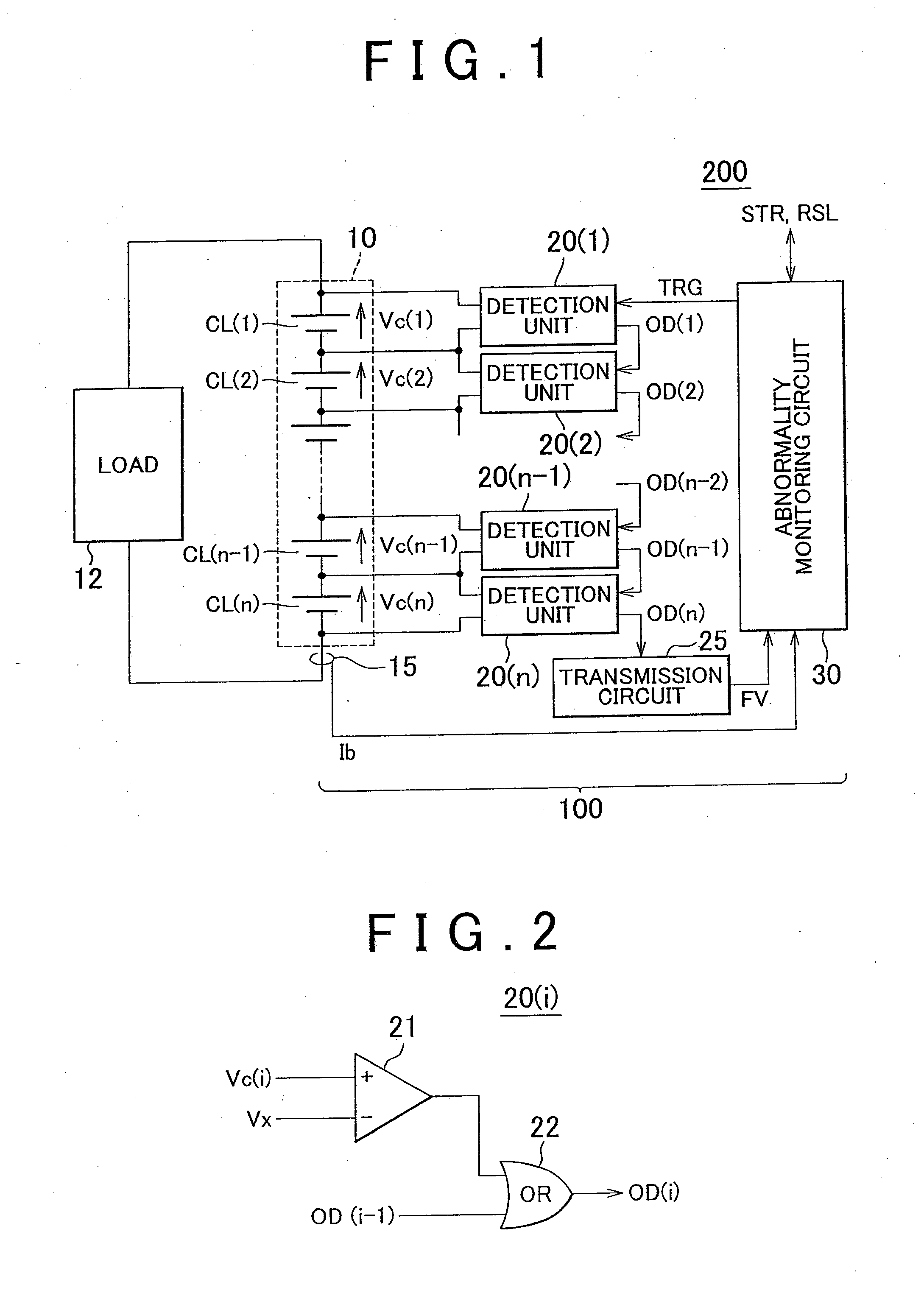
[0029]Referring to FIG. 1, an electric system 200 is installed on a vehicle, such as a hybrid vehicle or an electric vehicle, which has a mechanism capable of generating vehicle driving force using electric power. The electric system 200 has a battery assembly 10, an abnormality detecting system 100 for detecting an abnormality in the battery assembly 10, and a load 12.

[0030]The battery assembly 10 includes a plurality of battery cells CL(1)-CL(n) that are connected in series (n: an integer equal to or larger than 2). The battery assembly 10 supplies dc power to the load 12. Also, the battery assembly 10 is charged with dc power supplied from the load 12.

[0031]The load 12 includes a motor (not...


PUM


Abstract

An abnormality detecting system sequentially compares the output voltages of n-piece battery cells that are connected in series, with a criteria voltage, at respective points in time Tv1-Tvn, and produces a determination signal indicative of the presence or absence of any battery cell whose voltage becomes lower than the criteria voltage at time Tvc. The battery current Ib is sampled a predetermined number of times at intervals of a predetermined sampling cycle period ΔTi. The current sampling times Ti1-Ti3 are provided within a period that lies inside a voltage sampling period Ta-Tb including the above-indicated times Tv1-Tvn, with a given period of time (ΔTi−2) or less provided at each side of the period. When detecting an increase in the internal resistance based on a comparison between the maximum value of the current sampling values and a criteria current, the abnormality detecting system corrects the criteria current in view of a current variation in a half of the sampling cycle period due to current ripple.

Description

BACKGROUND OF THE INVENTION[0001]1. Field of the Invention[0002]The invention relates to an abnormality detecting system for a battery assembly, and more particularly to a technology of detecting an increase in the internal resistance of any battery cell in the battery assembly having a plurality of battery cells connected in series.[0003]2. Description of the Related Art[0004]A battery assembly in which a multiplicity of battery cells or battery modules are connected in series has been generally used. The battery assembly of this type is used in a hybrid vehicle, or the like, as a power source for driving an electric motor.[0005]In a battery assembly as described in Japanese Patent Application Publication No. 2005-345124 (JP-A-2005-345124), an A / D converter is shared among a plurality of battery modules. In particular, JP-A-2005-345124 discloses a data collection system having first A / D converters for detecting voltage values and a second A / D converter for detecting current values,...

Claims


Application Information

Patent Timeline
Patent Type & Authority Applications(United States)
IPC IPC(8): G01R31/36B60L50/16
CPCB60L3/0046B60L11/14G01R31/3658G01R31/3662Y02T10/70H01M10/482H02J7/0021Y02T10/7077H01M10/4207B60L50/16G01R31/396G01R31/389Y02T10/7072Y02E60/10H02J7/0013H02J7/0048H02J7/005
Inventor ISHISHITA, TERUO
Owner TOYOTA JIDOSHA KK
Learn More