

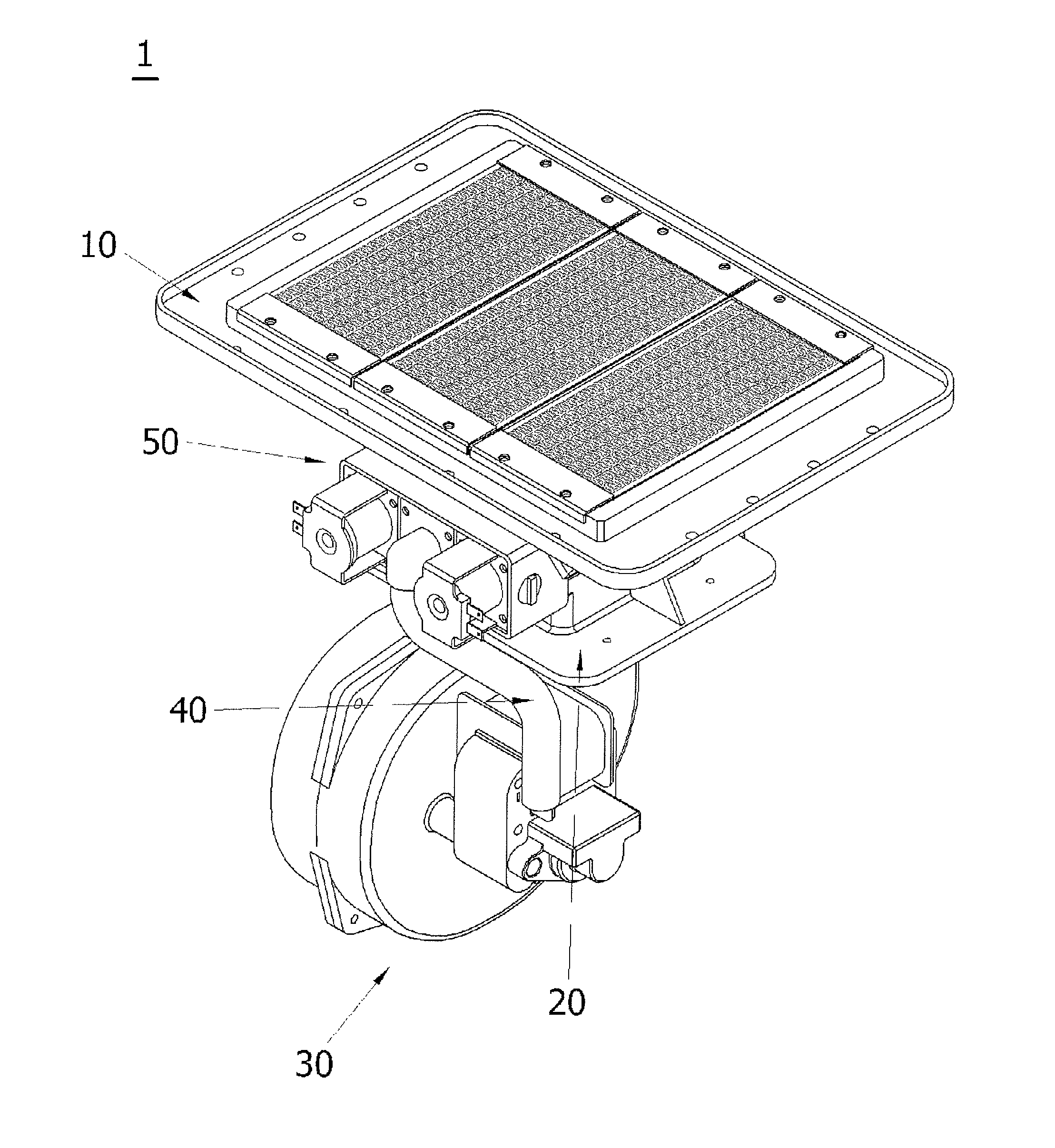
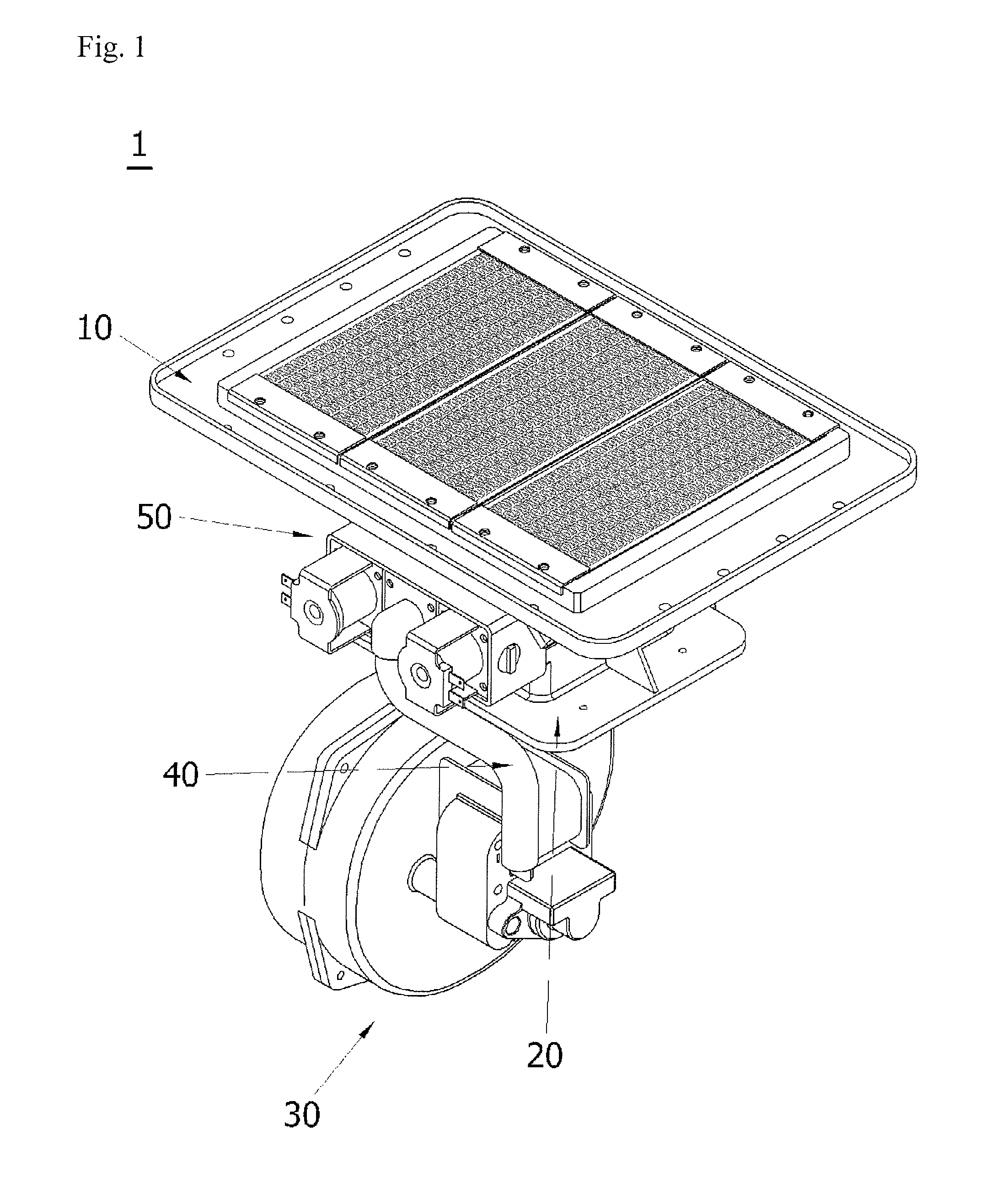
Flame hole unit structure of a gas burner
a technology of flame hole unit and burner, which is applied in the manufacture of burners, combustion types, burners, etc., can solve the problems of increased material cost, unsatisfactory combustion, damage to flame holes, etc., and achieve the effect of reducing time and cost consumed in the manufacture of gas burners, simplifying the structure of the flame hole unit of the burner, and easy manufacturing
- Summary
- Abstract
- Description
- Claims
- Application Information
AI Technical Summary
Benefits of technology
Problems solved by technology
Method used
Image

Examples
Embodiment Construction
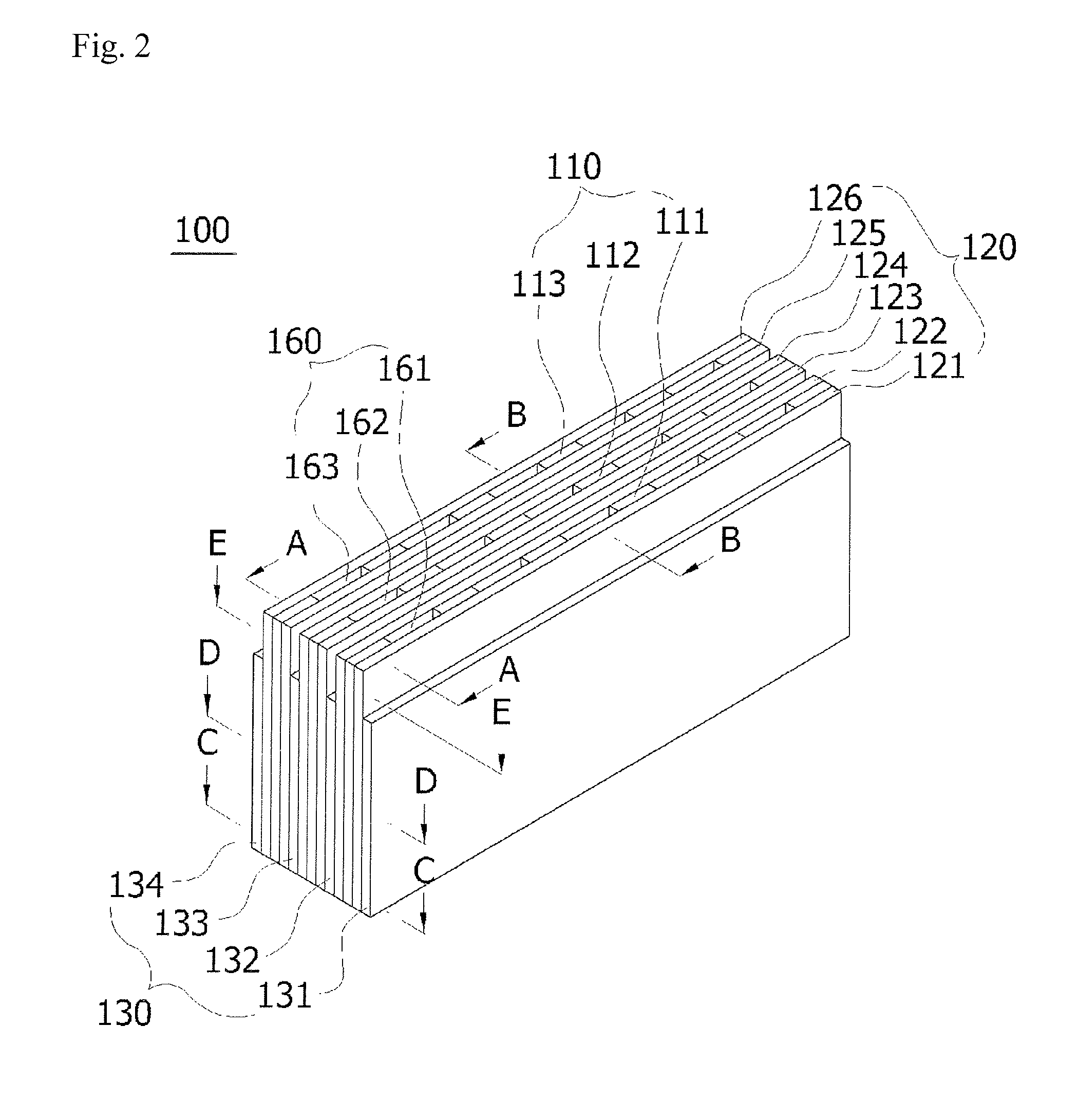
[0041]Reference will now be made in detail to the embodiments of the present invention, examples of which are illustrated in the accompanying drawings. However, it will be apparent to those skilled in the art that the following embodiments can be readily understood and modified into various types, and the scope of the present invention is not limited to the embodiments.
[0042]FIG. 2 is a perspective view of a flame hole unit structure of a gas burner in accordance with an exemplary embodiment of the present invention, FIG. 3 is a partially exploded perspective view of FIG. 2, FIG. 4 is a cross-sectional view taken along line A-A of FIG. 2, FIG. 5 is a cross-sectional view taken along line B-B of FIG. 2, FIG. 6 is a cross-sectional view taken along line C-C of FIG. 2, FIG. 7 is a cross-sectional view taken along line D-D of FIG. 2, and FIG. 8 is a cross-sectional view taken along line E-E of FIG. 2.
[0043]A flame hole unit 100 of a gas burner in accordance with the present invention ha...
PUM
 Abstract
Description
Claims
Application Information