Stent and stent delivery system for side-branch locations in a conduit

a conduit and stent technology, applied in the field ofluminal implants, can solve the problems of releasing arteriosclerosis debris from the treatment area, difficult positioning of stents, and specific challenges of selected segments of the human vasculature, and achieves the effects of enhancing conformance, superior radial strength, and maintaining the dilated diameter of the renal vessel

Active Publication Date: 2012-09-27
TYCO HEALTHCARE GRP LP
View PDF0 Cites 4 Cited by
  • Summary
  • Abstract
  • Description
  • Claims
  • Application Information

AI Technical Summary

Benefits of technology

[0009]A renal stent comprises a substantially cylindrical segment which is deployed in the renal vessel and a flared segment which is deployed in ostial and aortic regions of the vessel. The substantially cylindrical segment provides superior radial strength for maintaining dilated diameter of the renal vessel. The flared segment, which is formed by a plurality of slits extending through the sidewall of the stent, expands to conform to the ostial and aortic regions of the vessel. The flared segment can be balloon dilated to enhance conformance of the flared stented segment to the ostial and aortic regions. A stent delivery system capable of delivering and deploying the substantially cylindrical segment and the flared segment is also provided.

Problems solved by technology

However, selected segments of the human vasculature present specific challenges due to their shape and configuration.
In addition, stents are hard to position on a consistent basis at the precise ostial location desired, and placement of renal stents can release arteriosclerotic debris from the treatment area.
Such debris can flow distally into the kidney and embolize, causing impaired renal function.
However, existing stents are hard to flare with existing expansion means.
This need for high stent strength makes suitable stents difficult to flare at the ostium.

Method used


Image

  • Stent and stent delivery system for side-branch locations in a conduit
  • Stent and stent delivery system for side-branch locations in a conduit
  • Stent and stent delivery system for side-branch locations in a conduit

Examples


Embodiment Construction

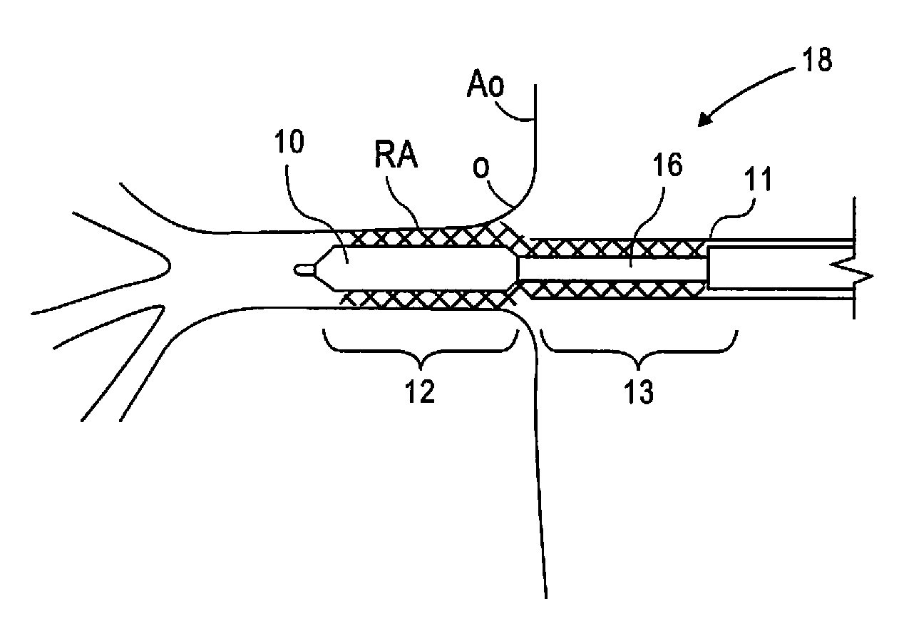
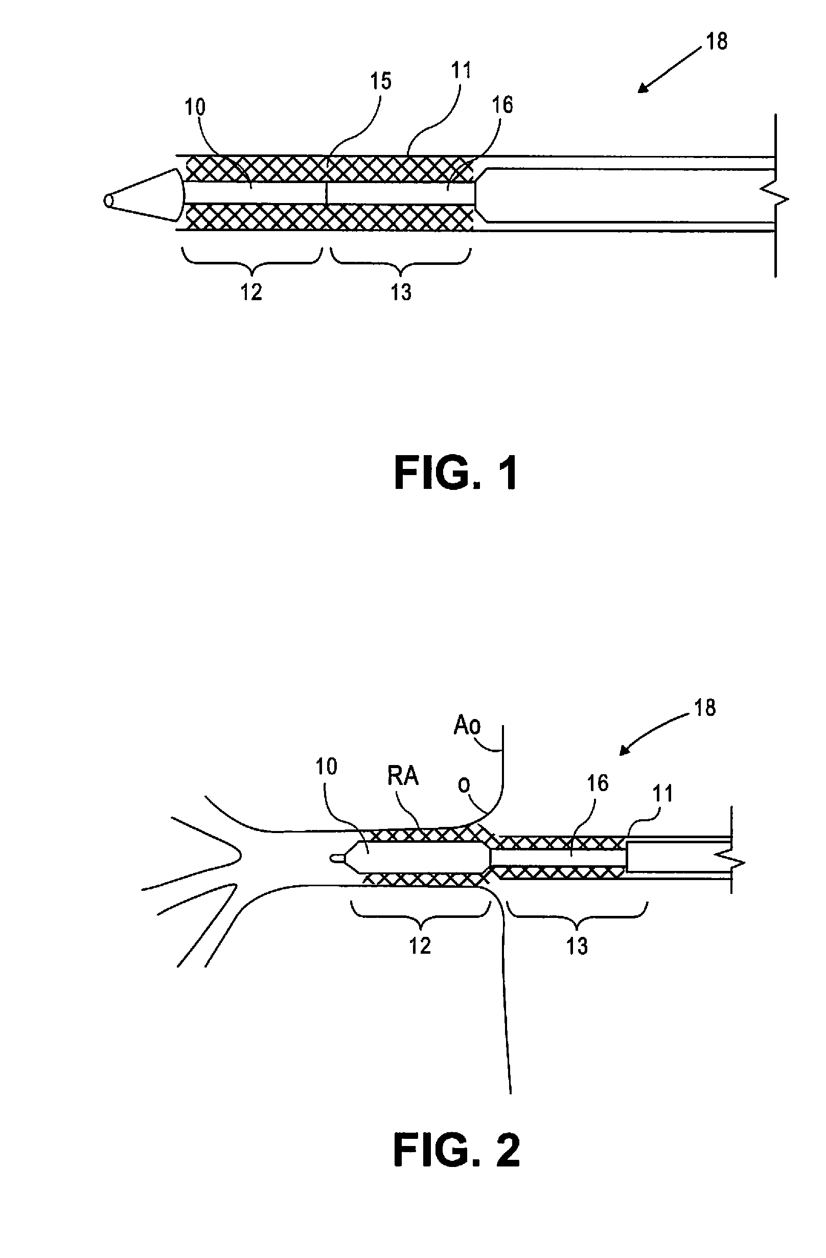
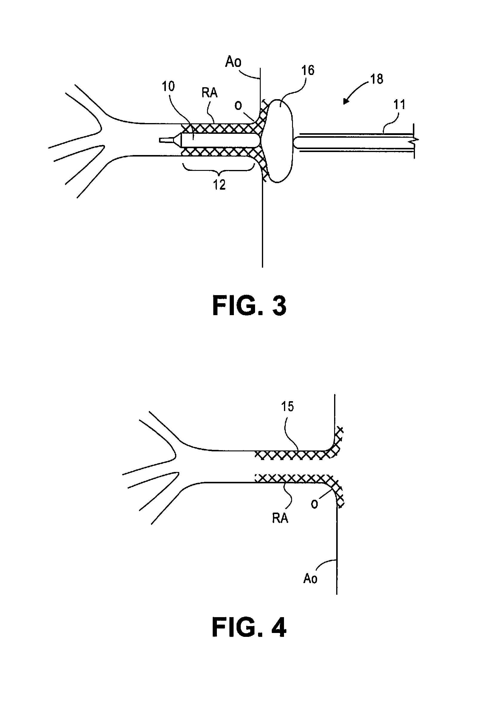
[0019]FIG. 1 illustrates a stent 15 in accordance with the present disclosure. Stent 15 comprises a substantially cylindrical stent segment 12 and a flared stent segment 13. Substantially cylindrical stent segment 12 may be balloon expandable and may comprise stainless steel alloys, cobalt chrome alloys, titanium, tantalum, platinum, gold, or other materials or their alloys as are known in the art. Flared stent segment 13 may be self expanding and may be comprise high elastic limit materials such as Elgiloy, cobalt chrome alloys, engineering polymers such as polyimide, PEEK (polyetheretherketone), polycarbonate, liquid crystal polymer, polyester, or other materials as are known in the art. The flared stent segment 13 may comprise so-called superelastic or shape-memory metals such as nitinol. Shape-memory metal stents can self-expand when thermo mechanically processed to exhibit superelastic material properties. Such shape-memory stents can also self-expand through use of a pre-progr...


PUM


Abstract

A stent includes a substantially cylindrical segment which is deployed in the renal vessel and a flared segment which is deployed in ostial and aortic regions of the vessel. The substantially cylindrical segment provides superior radial strength for maintaining dilated diameter of the renal vessel. The flared segment, which is formed by plurality of slits extending through the sidewall of the stent, expands to conform to the ostial and aortic regions of the vessel. The flared segment can be balloon dilated to enhance conformance of the flared stented segment to the ostial and aortic regions. A stent delivery system capable of delivering and deploying the substantially cylindrical segment and the flared segment is also disclosed.

Description

FIELD OF THE INVENTION[0001]The present invention relates to luminal implants, and, more particularly, to stents for use in treating vascular disease.BACKGROUND OF THE INVENTION[0002]Stents are widely used for supporting a lumen structure in a patient's body. For example, a stent may be used to maintain patency of a coronary artery, other blood vessel or other body lumen such as the ureter, urethra, bronchus, esophagus, or other passage. A stent is typically a metal, tubular structure, although polymer stents are known. Stents can be permanent enduring implants, or can be bioabsorbable at least in part. Bioabsorbable stents can be polymeric, bio-polymeric, ceramic, bio-ceramic, or metallic, and may elute over time substances such as drugs.[0003]In certain stent designs, the stent is an open-celled tube that is expanded by an inflatable balloon at the deployment site. Another type of stent is of a “self-expanding” type. A self-expanding stent does not use a balloon or other source of...

Claims


Application Information

Patent Timeline
Patent Type & Authority Applications(United States)
IPC IPC(8): A61F2/82
CPCA61F2/89A61F2/915A61F2/958A61F2002/821A61F2220/0058A61F2002/91591A61F2250/0039A61F2/82A61F2002/91575
Inventor MA, JIANLUTATALOVICH, JOE
Owner TYCO HEALTHCARE GRP LP
Why Eureka
Try Eureka