Corneal implant for refractive correction

a corneal implant and refractive correction technology, applied in the field of corneal implants for refractive correction, can solve the problems of unfocused image, eye impair the ability of the eye to focus an image, and general inconvenien

Inactive Publication Date: 2012-09-27
ACUFOCUS
View PDF0 Cites 91 Cited by
  • Summary
  • Abstract
  • Description
  • Claims
  • Application Information

AI Technical Summary

Benefits of technology

[0026]For purposes of summarizing the invention, certain aspects, advantages and novel features of the invention are described herein. It is to be understood that not all such advantages may be achieved in accordance with any particular embodiment of the invention. Thus, the invention may be embodied or carried out in a manner that achieves or optimizes one advantage or group of advantages as taught herein without necessarily achieving other advantages as may be taught or suggested herein.

Problems solved by technology

Unfortunately, several common defects in the eye impair the ability of the eye to focus an image as discussed above.
Due to a limit in the amount of deformation of the intraocular lens, however, the point of focus for near objects still falls behind the retina, resulting in an unfocused image.
While the foregoing treatments of poor vision due to refractive error or mismatch between refraction and other eye dimension work for most patient, they are generally inconvenient.
For example, glasses can be lost or damaged when removed, e.g., for sleeping or to be exchanged for sunglasses.
Similarly, contact lenses are inconvenient in that they need to be kept clean and periodically replaced.
Some patients find glasses and contact lenses uncomfortable and would prefer not to wear them.
While the use of these devices recently has been reduced by the introduction of laser surgery (e.g., LASIK and similar procedures), many patients are uncomfortable with these procedures because they physically change the eye (e.g. remove tissue from the eye) and thus are irreversible.

Method used


Image

  • Corneal implant for refractive correction
  • Corneal implant for refractive correction
  • Corneal implant for refractive correction

Examples


Embodiment Construction

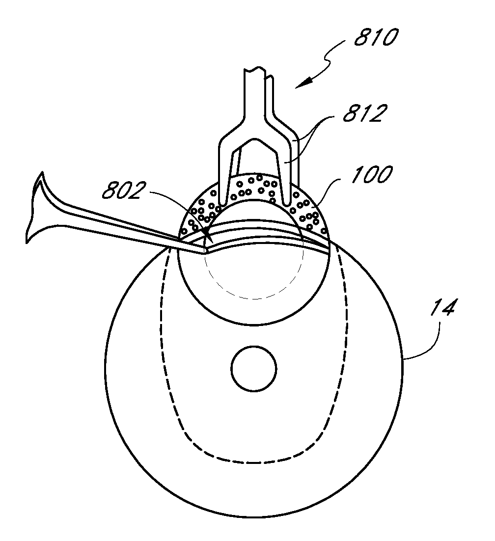
[0052]This application is directed to devices and methods that compensate for refractive error of a patient's eye. In some embodiments discussed below, a device that is capable of compensating for such refractive errors is an intra corneal lens. The corneal lenses discussed herein can be deployed within the cornea using a variety of techniques and, as such, the term “inlay” or “corneal inlay” is sometimes used. Other ocular devices and corneal lenses that are suitable for compensating for refractive error or otherwise improving a patient's vision can be placed on or in the cornea, e.g., on or in the epithelium of the eye.

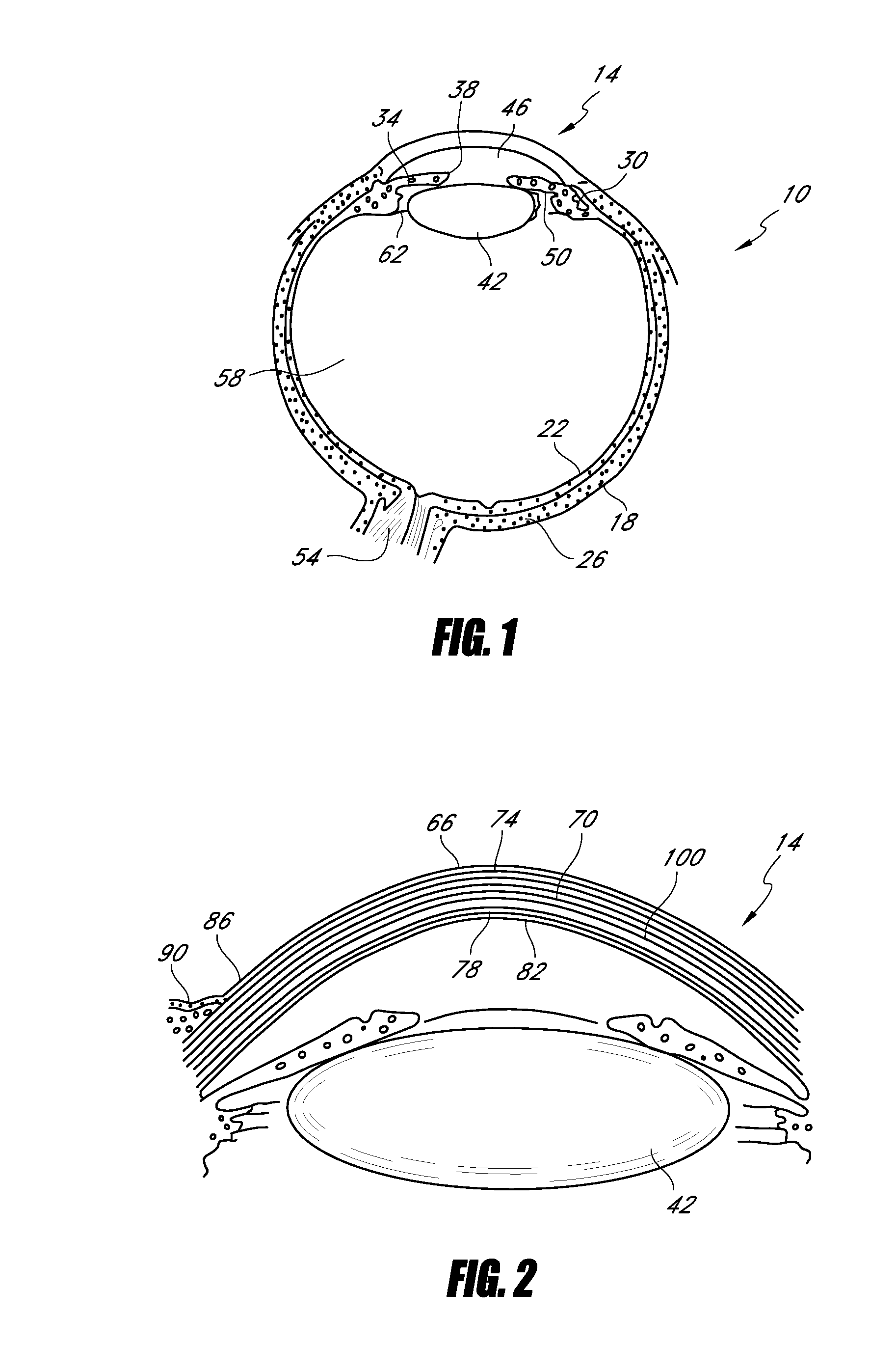
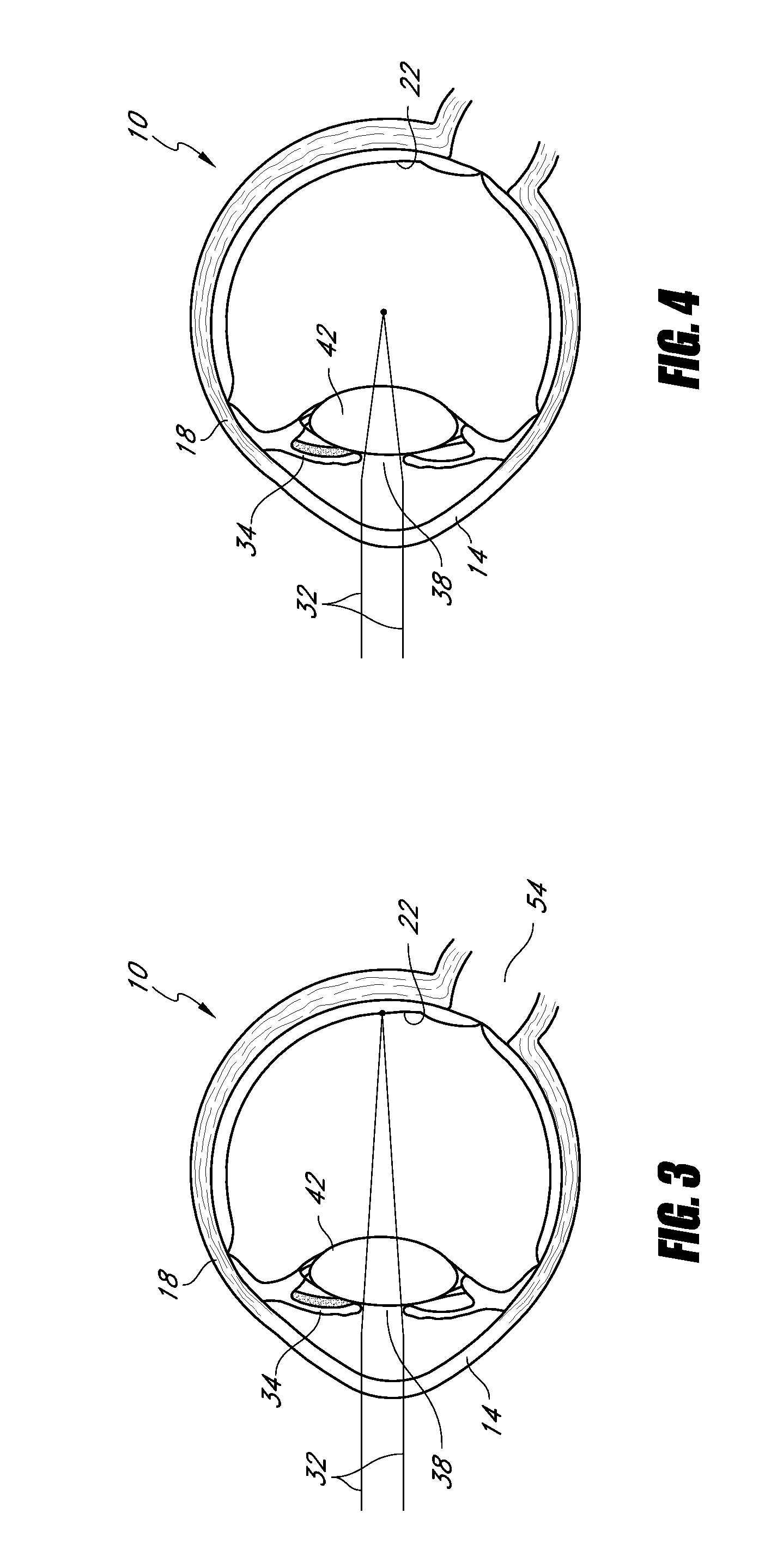
[0053]Prior to discussing the details of various embodiments of such an ocular device, the effects of refractive errors are set forth in connection with FIGS. 1-4. Thereafter, a variety of embodiments that compensate for refractive error, some of which additionally provide increased depth of field, will be discussed in connection with FIGS. 5-12. Various techniques ...


PUM


Abstract

A corneal implant adapted for implantation between layers of a cornea to focus an image on a retina of an eye includes an inlay, an outer perimeter, and a clear central region capable of refracting light to compensate for a refractive error of an eye. The inlay also has an annular opaque region comprising a plurality of holes or otherwise being adapted to transport nutrients. The annular opaque region extends from the outer circumference of the inlay to the clear central portion. The opaque region extends over a minority of the surface area of the implant. The anterior and posterior surfaces of the inlay are configured to abut adjacent layers of the cornea.

Description

CROSS-REFERENCE TO RELATED APPLICATIONS[0001]This application claims the benefit of U.S. Provisional Application No. 61 / 266,853, filed Dec. 4, 2009, the entirety of which is hereby incorporated by reference.BACKGROUND OF THE INVENTION[0002]1. Field of the Invention[0003]This application is directed to devices that can be deployed within a human cornea to compensate for at least one of refractive error and loss of accommodation, and to related methods.[0004]2. Description of the Related Art[0005]When a human eye focuses on objects, light rays from the object converge at the retina, located at the back of the eye. Such convergence of light rays is due to accommodation of the crystalline lens and refraction at the anterior surface of the cornea and at the interfaces between the cornea, the aqueous humor, the crystalline lens, and the vitreous humor. In the normal eye, light rays from a distant object which enter the eye parallel to an optical axis of the eye are focused (caused to conv...

Claims


Application Information

Patent Timeline
Patent Type & Authority Applications(United States)
IPC IPC(8): A61F2/14
CPCA61F2/14A61F2250/0098A61F2/145A61F2/15
Inventor CHRISTIE, BRUCE A.SILVESTRINI, THOMAS
Owner ACUFOCUS
Why Eureka
Try Eureka