
Air-fuel ratio control apparatus for an internal combustion engine

a control apparatus and internal combustion engine technology, applied in the direction of electrical control, process and machine control, instruments, etc., can solve the problems of heat deterioration/degradation of the three-way catalyst, and achieve the effect of reducing the degree of leanness, reducing and increasing the temperature of the catalys

Inactive Publication Date: 2012-09-27
TOYOTA JIDOSHA KK
View PDF19 Cites 7 Cited by
  • Summary
  • Abstract
  • Description
  • Claims
  • Application Information

AI Technical Summary

Benefits of technology

The present invention relates to an air / fuel ratio control apparatus for an internal combustion engine that includes a catalyst having an oxidization capability in an exhaust passage. The invention aims to prevent heat deterioration or degradation of the catalyst when carrying out a lean control after a rich control. The invention proposes a temporary lean control that controls the air / fuel ratio of the mixture formed in the combustion chamber to be an air / fuel ratio leaner than the stoichiometric air / fuel ratio by a predetermined degree, while the temperature of the catalyst is higher than a predetermined temperature. This reduces the amount of unburned fuel in the catalyst and prevents heat generation, thereby restraining heat deterioration or degradation of the catalyst.

Problems solved by technology

Accordingly, in some cases, the temperature of the three way catalyst exceeds a permissible temperature, and thus, a heat deterioration / degradation of the three way catalyst may occur.

Method used


Image

  • Air-fuel ratio control apparatus for an internal combustion engine
  • Air-fuel ratio control apparatus for an internal combustion engine
  • Air-fuel ratio control apparatus for an internal combustion engine

Examples


first embodiment

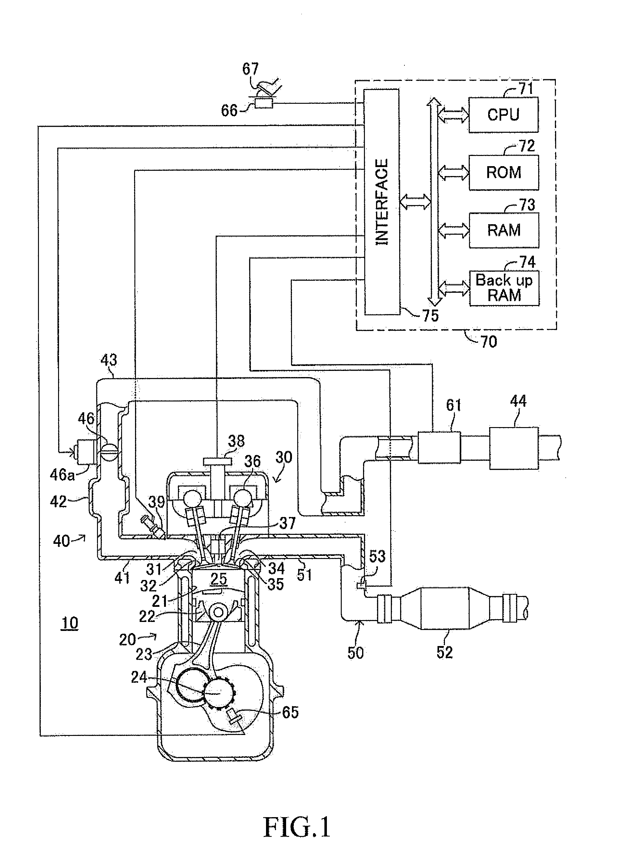
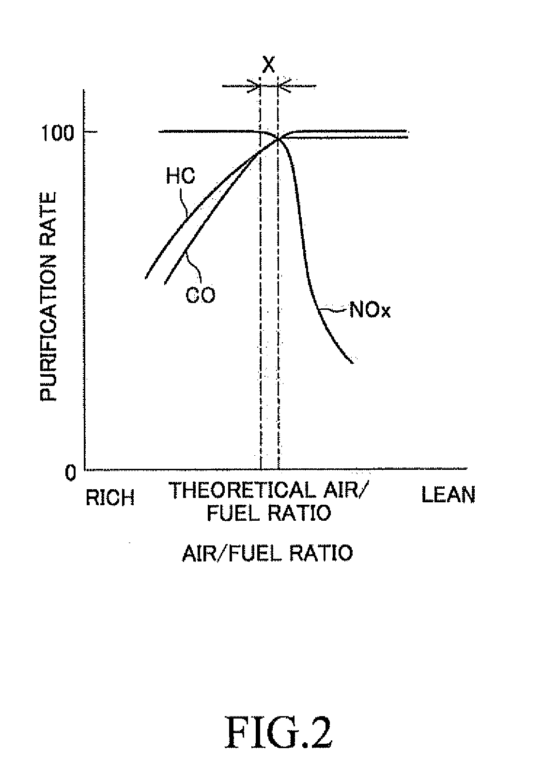
[0052]Meanwhile, as described above, the three way catalyst 52 simultaneously can purify NOx, CO, and HC at high purification efficiency when the air / fuel ratio of the exhaust gas flowing thereto is close to the stoichiometric air / fuel ratio. Thus, the air / fuel ratio of the mixture formed in the combustion chamber 25 (the air / fuel ratio of the mixture formed in the combustion chamber is simply referred to as “air / fuel ratio of mixture” hereinafter) is preferably controlled to be the stoichiometric air / fuel ratio in terms of maintaining high purification efficiency in the three way catalyst. In view of the above, an ordinary stoichiometric control for controlling the air / fuel ratio of the mixture to be the stoichiometric air / fuel ratio is carried out when the engine operation state (operation state of internal combustion engine) is in an ordinary state according to this embodiment (referred to as a “first embodiment” hereinafter).

[0053]That is, a quantity of the air taken into the co...

second embodiment

[0100]In the temporary stoichiometric control when the air / fuel ratio of the mixture is richer than the stoichiometric air / fuel ratio serving as the target air / fuel ratio, the base fuel injection quantity calculated as described above is decreased by the decreased quantity correction amount which is decreased by multiplying the decreased quantity correction amount read from the map in (A) of FIG. 3 by the correction coefficients K1 and K2 read from the maps in (A) of FIG. 13 and (B) of FIG. 13, and the decreased base fuel injection quantity is set to the target fuel injection quantity.

[0101]Thereafter, the fuel injection valve is controlled in such a manner that a fuel of the target fuel injection quantity set in this way is injected from the fuel injection valve 39.

[0102]On the other hand, in the temporary stoichiometric control according to the second embodiment, when the air / fuel ratio of the mixture is leaner than the stoichiometric air / fuel ratio serving as the target air / fuel...

third embodiment

[0112]In the temporary stoichiometric control when the air / fuel ratio of the mixture is richer than the stoichiometric air / fuel ratio serving as the target air / fuel ratio, the base fuel injection quantity calculated as described above is decreased by the decreased quantity correction amount which is decreased by multiplying the decreased quantity correction amount read from the map in (A) of FIG. 3 by the correction coefficients K1 and K3 read from the maps in (A) of FIG. 15 and (B) of FIG. 15, and the decreased base fuel injection quantity is set to the target fuel injection quantity.

[0113]Thereafter, the fuel injection valve is controlled in such a manner that a fuel of the target fuel injection quantity set in this way is injected from the fuel injection valve 39.

[0114]On the other hand, in the temporary stoichiometric control according to the third embodiment, when the air / fuel ratio of the mixture is leaner than the stoichiometric air / fuel ratio serving as the target air / fuel ...


PUM


Abstract

After rich control for controlling the air / fuel ratio of a mixture to be an air / fuel ratio richer than stoichiometric air / fuel ratio, lean control is carried out so that air / fuel ratio of the mixture formed in the combustion chamber is controlled to be an air / fuel ratio leaner by a predetermined degree than the stoichiometric air / fuel ratio, or the air / fuel ratio of the mixture is controlled to temporarily be the air / fuel ratio leaner by the predetermined degree than the stoichiometric air / fuel ratio. If lean control is carried out after rich control is finished, temporary lean control provides that a degree of how much the air / fuel ratio of the mixture is leaner than the stoichiometric air / fuel ratio when the air / fuel ratio of the mixture is controlled to be the air / fuel ratio leaner than the stoichiometric air / fuel ratio in lean control is lower than the predetermined degree according to the temperature of a catalyst.

Description

TECHNICAL FIELD[0001]The present invention relates to a control apparatus for an internal combustion engine.BACKGROUND ART[0002]Japanese Patent Application Laid-open No. S63-45444 discloses an air / fuel ratio control apparatus for an internal combustion engine of spark ignition type including a three-way catalyst in an exhaust passage. This air / fuel ratio control apparatus decreases a temperature of an exhaust gas discharged from combustion chambers by increasing the quantity of a fuel injected from fuel injection valves compared to an ordinary quantity, namely a quantity increase of the fuel injection quantity when a temperature of the three-way catalyst is higher than a target temperature, to thereby restraining the temperature rise of the catalyst in order to prevent the temperature from rising to be an excessively high temperature exceeding a predetermined temperature.[0003]According to the above-mentioned publication, as long as a period in which an operation state of the intern...

Claims


Application Information

Patent Timeline
Patent Type & Authority Applications(United States)
IPC IPC(8): F02D41/26F01N3/10F02D41/32
CPCF02D41/0235F02D41/1475F02D41/025F02D2200/0802F02D41/024F02D2041/0265
Inventor YOSHIOKA, MAMORU
Owner TOYOTA JIDOSHA KK
Learn More