Method of producing biosoluble inorganic fiber

a biosoluble inorganic fiber and fiber technology, applied in glass making apparatus, manufacturing tools, instruments, etc., can solve the problems of difficult stably producing fibers, difficult to obtain fibers having a small fiber diameter, etc., and achieve the effect of stably producing biosoluble inorganic fibers

Inactive Publication Date: 2012-10-04
NICHIAS CORP
View PDF10 Cites 26 Cited by
  • Summary
  • Abstract
  • Description
  • Claims
  • Application Information

AI Technical Summary

Benefits of technology

[0011]The invention makes it possible to stably produc

Problems solved by technology

However, if the raw material has a silica content of 70 wt % or more, it is difficult to obtain fibers having a small fiber diameter (diameter) due to an increase in viscosit

Method used


Image

  • Method of producing biosoluble inorganic fiber
  • Method of producing biosoluble inorganic fiber
  • Method of producing biosoluble inorganic fiber

Examples


experiment 1

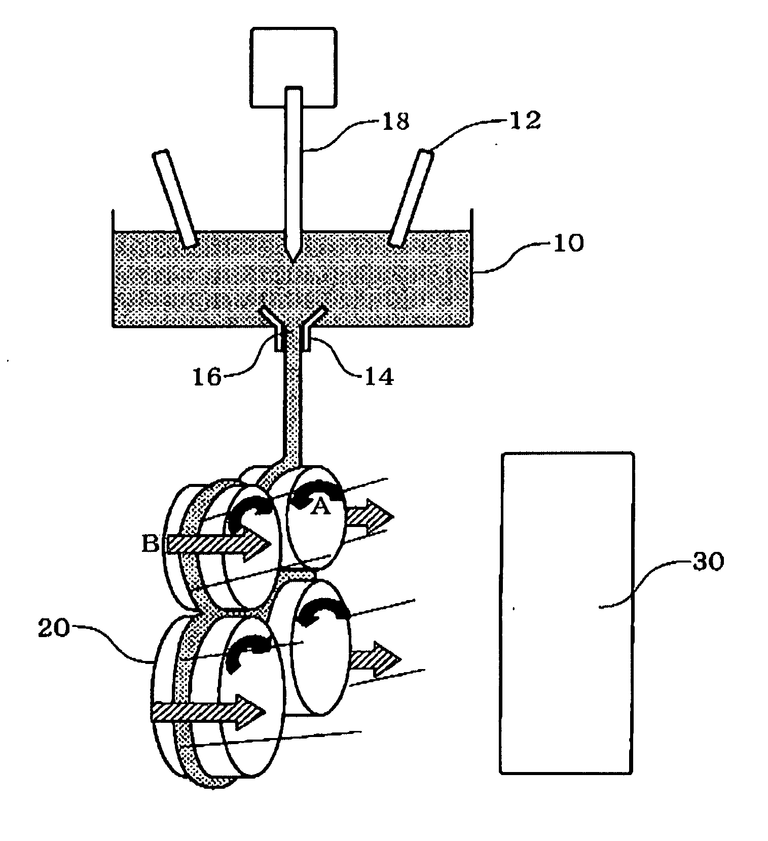
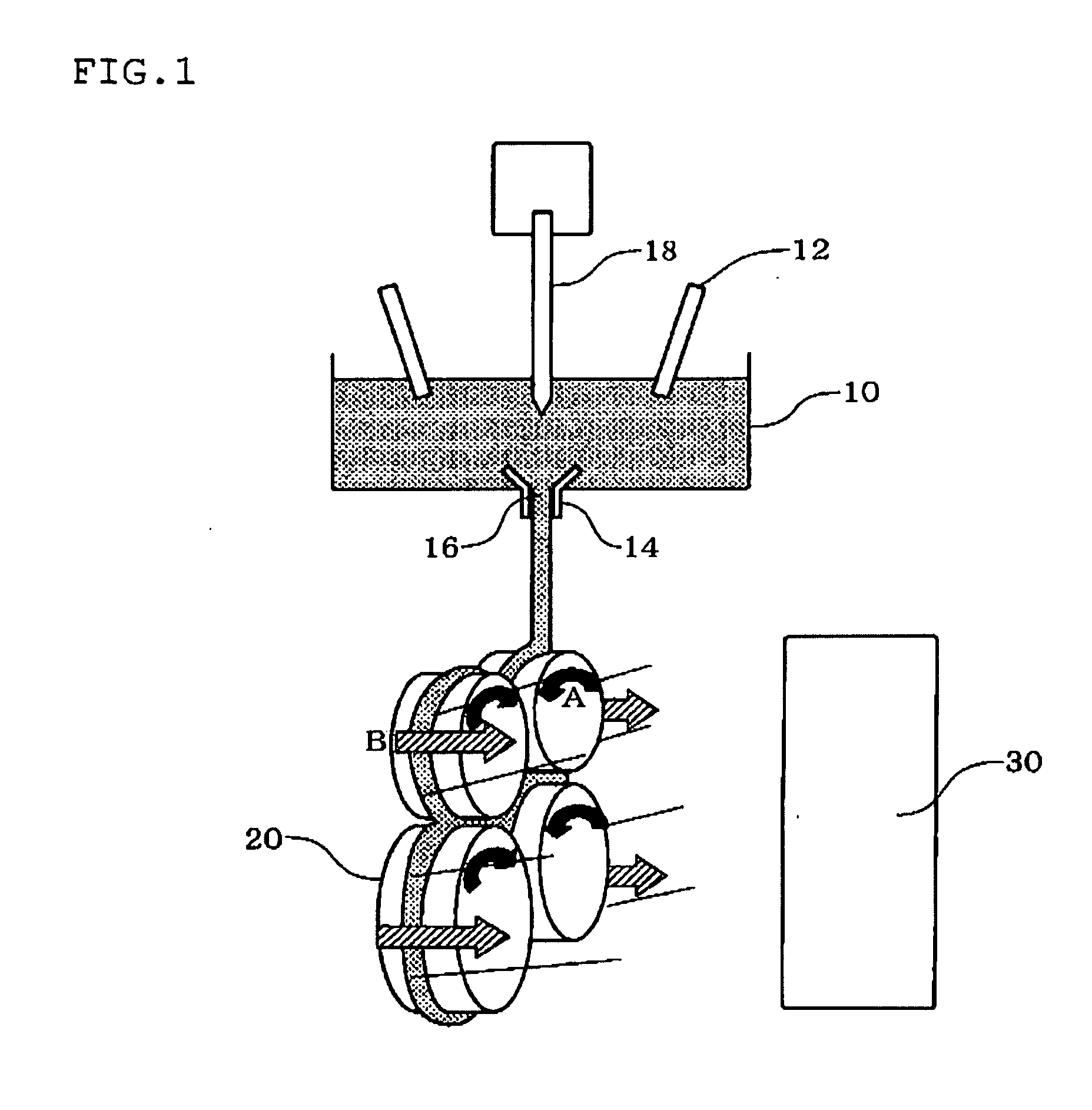
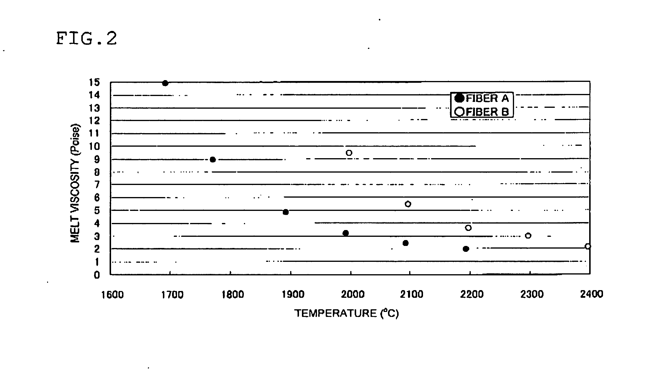
[0051]Raw materials for fibers A and B having a composition shown in Table 1 were heated and melted at 1700 to 2400° C. in a container by applying an electric power of 0.15 kW / kg to electrodes to obtain a melt having a melt viscosity of 1 to 15 poise. FIG. 2 illustrates the relationship between the melt viscosity of the fibers A and B and the temperature.

[0052]The resulting melt was supplied to a rotor rotating at an acceleration of 74, 115, or 259 km / s2 via an orifice of the container at a speed of about 300 to 600 kg / h. The amount of the melt supplied was adjusted within a certain range using a control rod. Fibers were produced while blowing air around the rotors. FIG. 3 illustrates the relationship between the melt viscosity and the average diameter of the resulting fibers A and B.

[0053]The fibers A produced at a melt viscosity of 3 poise and an acceleration of 259 km / s2 had a low flakes (shot) content of 40 to 50%.

[0054]The following measuring methods were used in the experiment...

experiment 2

[0058]Fibers A were produced in the same manner as in Experiment 1 at a melt viscosity of 5 poise and an acceleration of 259 km / s1. In Experiment 2, a change in the amount of the melt supplied to the rotor with time was measured with or without the control rod. The rod was lowered as the diameter of the hole of the orifice increased. The results are shown in FIG. 4 and Table 2. The height of the rod is also shown in FIG. 4. It was confirmed that a change in the amount of the melt supplied to the rotor could be suppressed by utilizing the rod, whereby the fiber diameter was reduced.

TABLE 2Amount of meltStandardsupplieddeviationFiber diameterRod was used340-550363.5-3.9Rod was not used330-6701203.5-5.1

experiment 3

[0059]Fibers A were produced in the same manner as in Experiment 1 at a melt viscosity of 5 poise and an acceleration of 259 km / s2. In Experiment 3, the supply temperature and the viscosity of the melt were measured while changing the power applied to the electrodes. The results are shown in Table 3.

TABLE 3Fibers AFibers BAppliedSupplyMeltingSupplyMeltingpowertemperatureviscositytemperatureviscosity(kW / kg)(° C.)(poise)(° C.)(poise)0.10163117.4187714.00.15167814.0191911.80.20172411.319619.90.2517709.120038.40.5020023.522133.80.6020952.422972.90.7021881.723812.2

[0060]Inorganic fibers produced by the method according to the invention can be used for various applications as a heat insulator or an alternative to asbestos, for example.


PUM

PropertyMeasurementUnit
Temperatureaaaaaaaaaa
Material consumption rateaaaaaaaaaa

Abstract

A method of producing inorganic fibers includes heating and melting an inorganic raw material that includes 70 wt % or more of silica and 10 wt % to 30 wt % of magnesia and calcia in total in a container to obtain a melt having a melt viscosity of 15 poise or less, supplying the melt to a rotor that rotates at an acceleration of 70 km/s2 or more, drawing the melt due to a centrifugal force caused by rotation of the rotor to obtain fibers, blowing the fibers off by blowing air around the rotor, and collecting the fibers to obtain fibers having an average fiber diameter of 5 μm or less.

Description

TECHNICAL FIELD[0001]The invention relates to a method of producing biosoluble inorganic fibers.BACKGROUND[0002]Inorganic fibers are lightweight, have a good handling capability, and exhibit excellent heat resistance. Therefore, inorganic fibers are used as a heat-resistant seal material, for example. In recent years, it has been pointed out that health problems may occur due to inhalation of inorganic fibers into to a lung of a living body. Therefore, biosoluble inorganic fibers that do not cause (or rarely cause) health problems upon inhalation have been developed (see Japanese Patent No. 3753416 and JP-T-2005-514318, for example).[0003]JP-A-2010-202983 and JP-A-2010-189798 disclose producing inorganic fibers having an average fiber diameter of 100 to 2000 nm or 3 to 50 μm by an electrospinning method. JP-A-2003-105658 discloses producing inorganic fibers having an average fiber diameter of 4 to 10 μm and containing alumina as the main component by a blowing method that produces f...

Claims


Application Information

Patent Timeline
IPC IPC(8): C03B37/05C03B37/07C03B37/06
CPCC03B5/26C03C2213/02C03C13/06C03B37/055D01F9/08D01D5/18C03B37/05C03C13/00
Inventor KITAHARA, HIDEKIMOCHIDA, TAKAHITONAKAJIMA, TAKASHIMIHARA, TETSUYAYONAIYAMA, KENKOBAYASHI, NOBORUABE, IKUONAGASE, HIDEO
Owner NICHIAS CORP
Why Eureka
Try Eureka