Grate clearing and ash removal system for gasification furnace

a gasification furnace and ash removal technology, which is applied in the direction of lighting and heating apparatus, combustion types, incinerator apparatus, etc., can solve the problems of feed screws pushing out over the top of the fuel pile, not moving the material successfully, and insufficient gravity alone to keep the grate clean, etc., to achieve the effect of longer run times

Inactive Publication Date: 2012-10-04
BENDER ROBERT J +2
View PDF11 Cites 8 Cited by
  • Summary
  • Abstract
  • Description
  • Claims
  • Application Information

AI Technical Summary

Benefits of technology

[0017]An object of the present invention is to provide an integrated three component approach to grate clearing, utilizing only a non-mechanical grate structure and existing components to achieve the grate clearing, wherein the success of the combination of these factors leads to longer run times, longer term combustion efficiency and load maintenance, less frequent shut down for grate maintenance, less ash fusion and clinkering, and less mechanical maintenance requirements.

Problems solved by technology

Natural mineral contents of fuels and tramp mineral materials accreted to the fuel tend to cause major problems maintaining good air flow, and therefore good quality combustion.
Steep angled grates attempt to use gravity to move the solid fuel and ash down the grate, but the gravity alone is not sufficient to keep the grate clean.
Steepness of the fuel grate in a gravity feed has to be in excess of the angle of repose of the material, which for ash, which is fairly dense is fairly steep resulting in the feed screws pushing out over the top of the fuel pile, and not moving the material successfully.
The consequence is the build up and melting of ash material on the grate, causing poor fuel utilization and decreasing system output, which requires the furnace to be shut down for manual grate maintenance, or have an elaborate moving or automated grate agitation approach to minimize the grate build up and ash fusion.
These “systems” are high cost and have high maintenance components which often breakdown, clog up, or ultimately fail to successfully stop the ash build up problem without frequent shut down and manual maintenance.

Method used


Image

  • Grate clearing and ash removal system for gasification furnace
  • Grate clearing and ash removal system for gasification furnace
  • Grate clearing and ash removal system for gasification furnace

Examples


Embodiment Construction

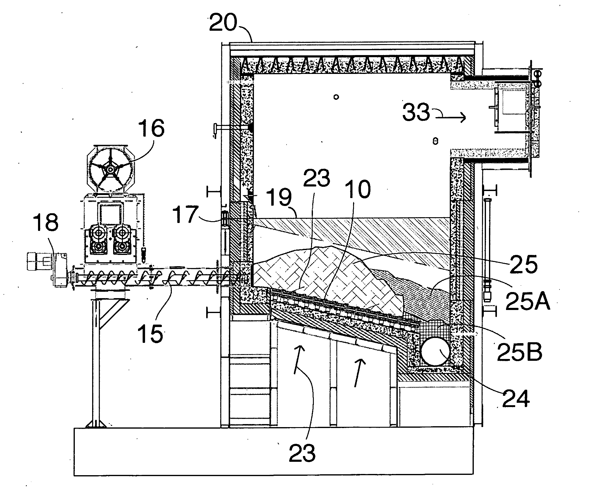
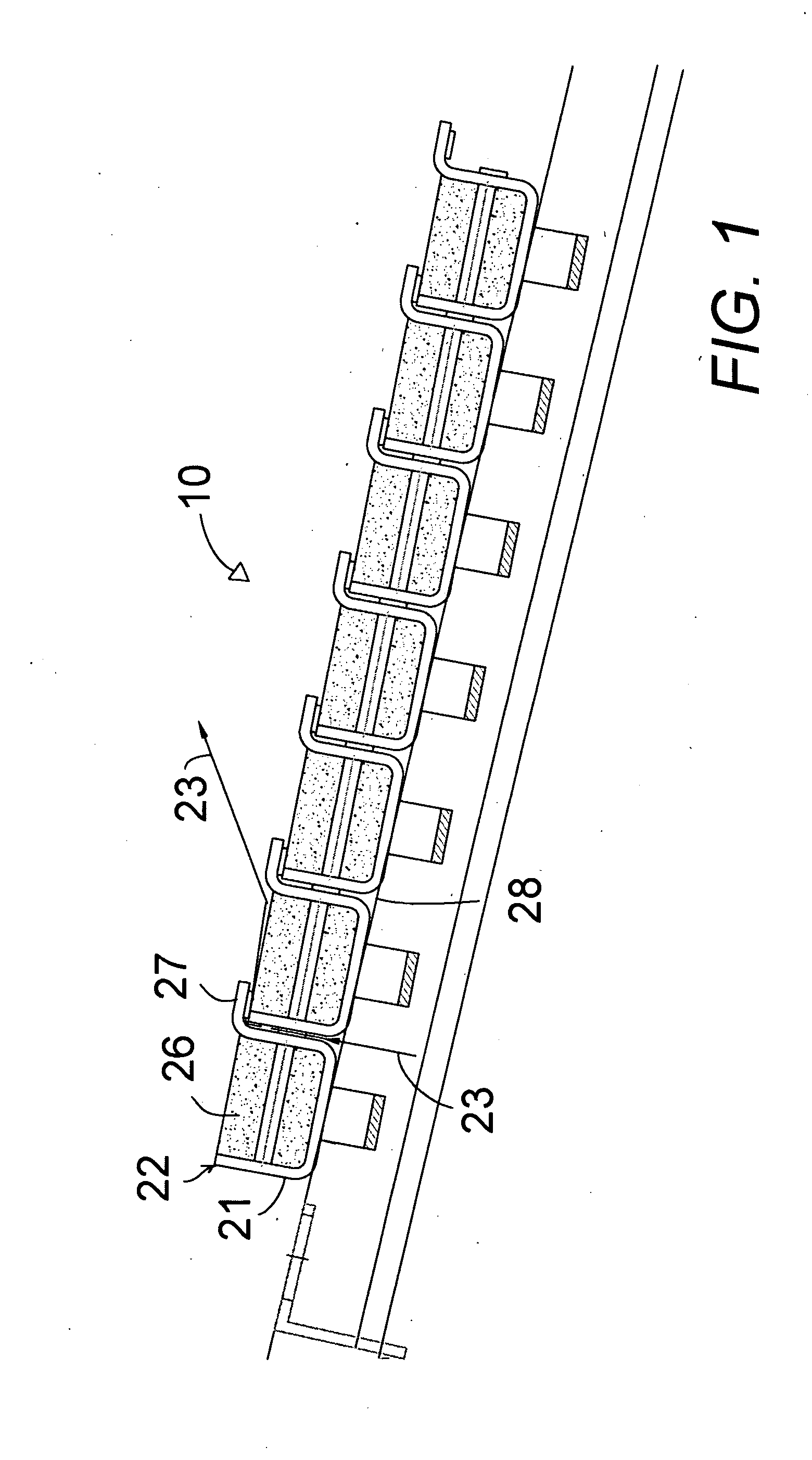
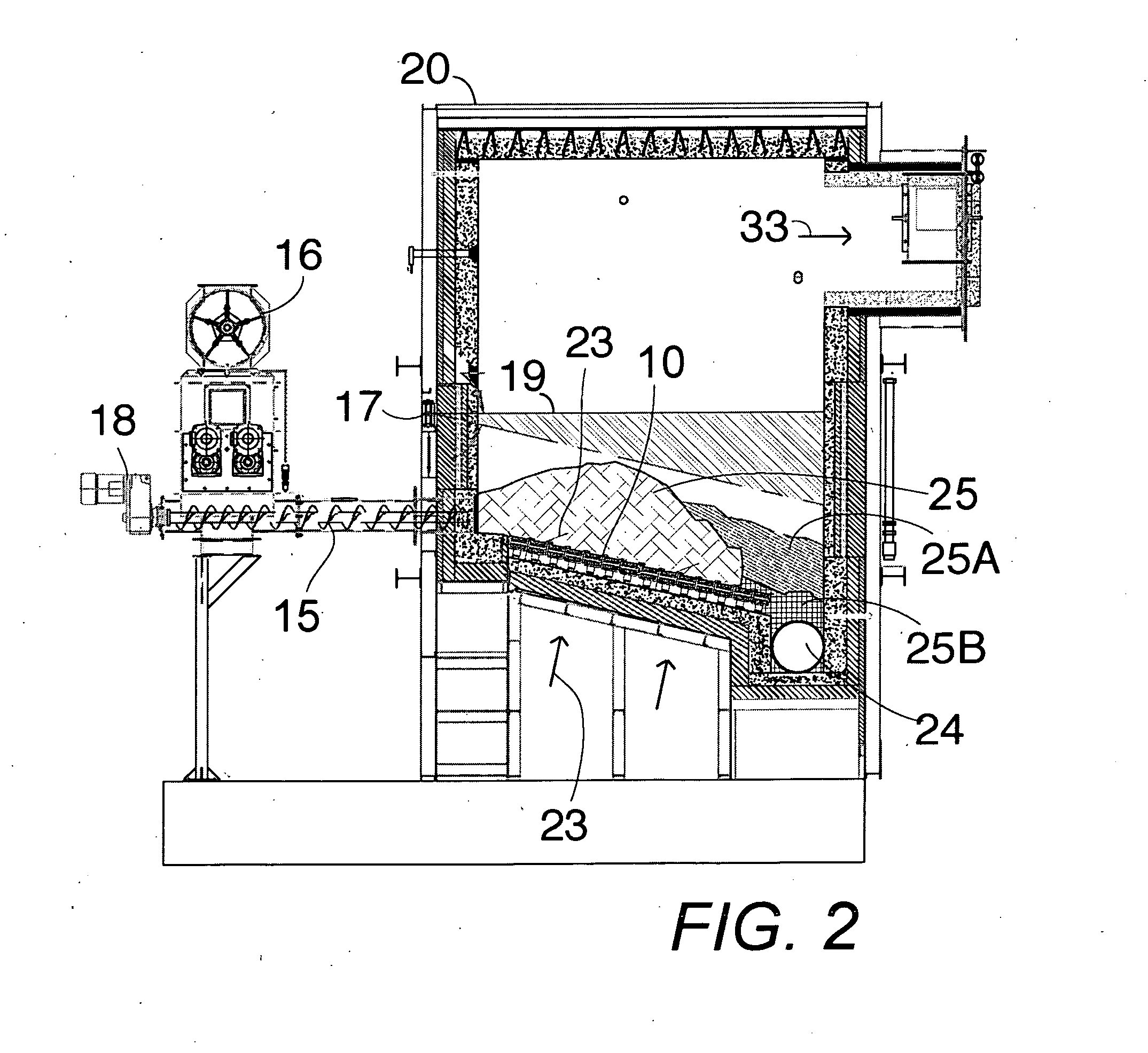
[0024]In FIGS. 1 and 3, an integrated system combines fuel grate structure 10 and angle and multiple feed auger 15 fuel movement components and under-fuel air flow directing components 27 for a grate clearing and fuel movement integrated system in a biomass gasification furnace.

[0025]In FIG. 1, the multiple feed screws 15 feed biomass fuel material 25 through a biomass fuel feed opening into a gasification chamber 20 of the biomass gasification furnace.

[0026]In FIG. 2, the fuel grate 10 comprises a series of interconnected grate elements 22 aligned in a linear array having aligned top surfaces 26. The grate extends from the biomass fuel feed opening through which the multiple feed screws 15 pass into and across the gasification chamber 20 angled downwardly at a slight acute angle from the horizontal so that the feed screws 15 press the fuel material 25 into and across the aligned top surfaces 26 of the grate elements to keep the bottom of the solid fuel moving along the aligned top ...


PUM


Abstract

A relatively level fuel grate surface angle cooperates with multiple feed screws that press solid fuel material into and across the grate surface to continually clear off the grate. Air spaces between each pair of adjacent grate elements for under fire air each have a ninety degree deflector flange at the top of the air space extending from one grate element across the air space and up and over an adjacent grate element to deflect under fire airflow across the adjacent grate element to act as a grate sweeper. The smooth curved surface of the deflector flange between grate elements facilitates movement of the fuel and ash material and prevents from one grate element to the next and prevents clogging of the airflow space.

Description

CROSS-REFERENCE TO RELATED APPLICATIONS[0001]Not Applicable.STATEMENT REGARDING FEDERALLY SPONSORED RESEARCH OR DEVELOPMENT[0002]Not Applicable.THE NAMES OF THE PARTIES TO A JOINT RESEARCH OR DEVELOPMENT[0003]Not Applicable.BACKGROUND OF THE INVENTIONField of the Invention[0004]The present invention relates to biomass fuel gasification chambers and particularly to a grate clearing and ash removal system and method for a gasification furnace; the system comprises a relatively level grate surface angle, multiple feed screws which press fuel material into and across the level grate surface, and 90 degree deflection of the under fire air, up through the grate bar spacing, and against a deflector changing the air flow to blow across the adjacent grate bar and act as a grate sweeper. Description of Related Art including information disclosed under 37 CFR 1.97 and 1.98[0005]The basic gasification furnace works by providing an automatic feed of wood chips or other solid fuel onto a sloped g...

Claims


Application Information

Patent Timeline
Patent Type & Authority Applications(United States)
IPC IPC(8): F23J1/00F23K3/14F23G5/027
CPCF23G5/002F23H1/02F23J1/00F23H15/00F23H7/04
Inventor BENDER, ROBERT J.TOMASI, JOHN P.NOVISKI, BRADLEY M.
Owner BENDER ROBERT J
Why Eureka
Try Eureka