Vehicle control apparatus and vehicle control method

a vehicle control and vehicle technology, applied in process and machine control, electrochemical generators, instruments, etc., can solve the problems of improving the overall fuel consumption of the vehicle control apparatus, and achieve the effect of improving the overall fuel consumption of the vehicle control devi

Active Publication Date: 2012-10-04
TOYOTA JIDOSHA KK
View PDF1 Cites 19 Cited by
  • Summary
  • Abstract
  • Description
  • Claims
  • Application Information

AI Technical Summary

Benefits of technology

[0005]There would thus be a requirement for utilizing the waste heat of fuel cells to heat up a heater core. There would also be a requirement for improving the overall fuel consumption of a vehicle control device that is configured to control a vehicle and warm up fuel cells.

Problems solved by technology

This arrangement desirably restricts the use of a different heating element, such as an electric heater, for heating up the flow of the cooling medium supplied to the heater core and decreases a required amount of electric power to be generated by the fuel cell and to be supplied to the different heating element, such as the electric heater, thus improving the overall fuel consumption of the vehicle control apparatus.

Method used


Image

  • Vehicle control apparatus and vehicle control method
  • Vehicle control apparatus and vehicle control method
  • Vehicle control apparatus and vehicle control method

Examples


embodiment

A. Embodiment

A1. SYSTEM CONFIGURATION

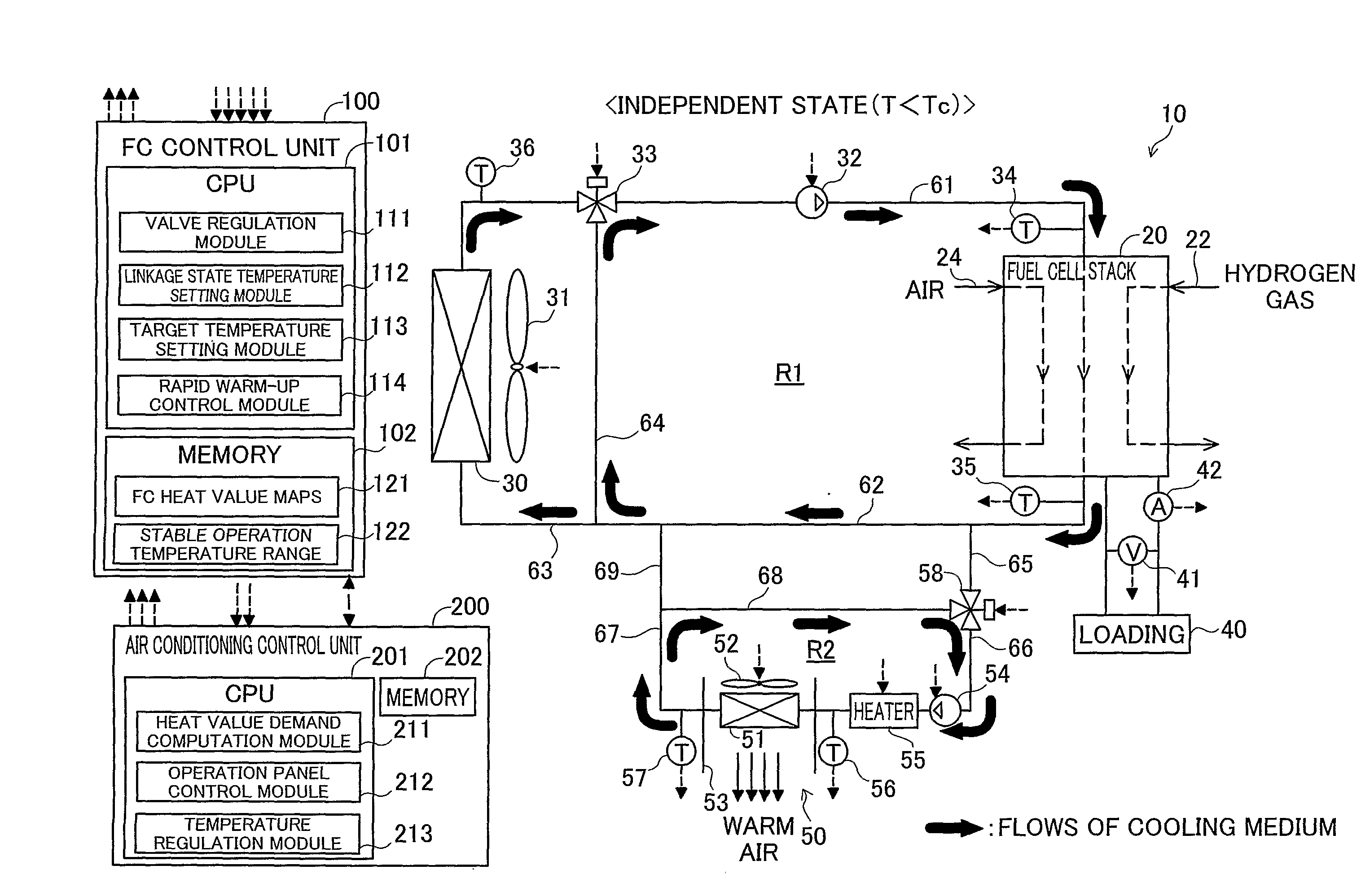
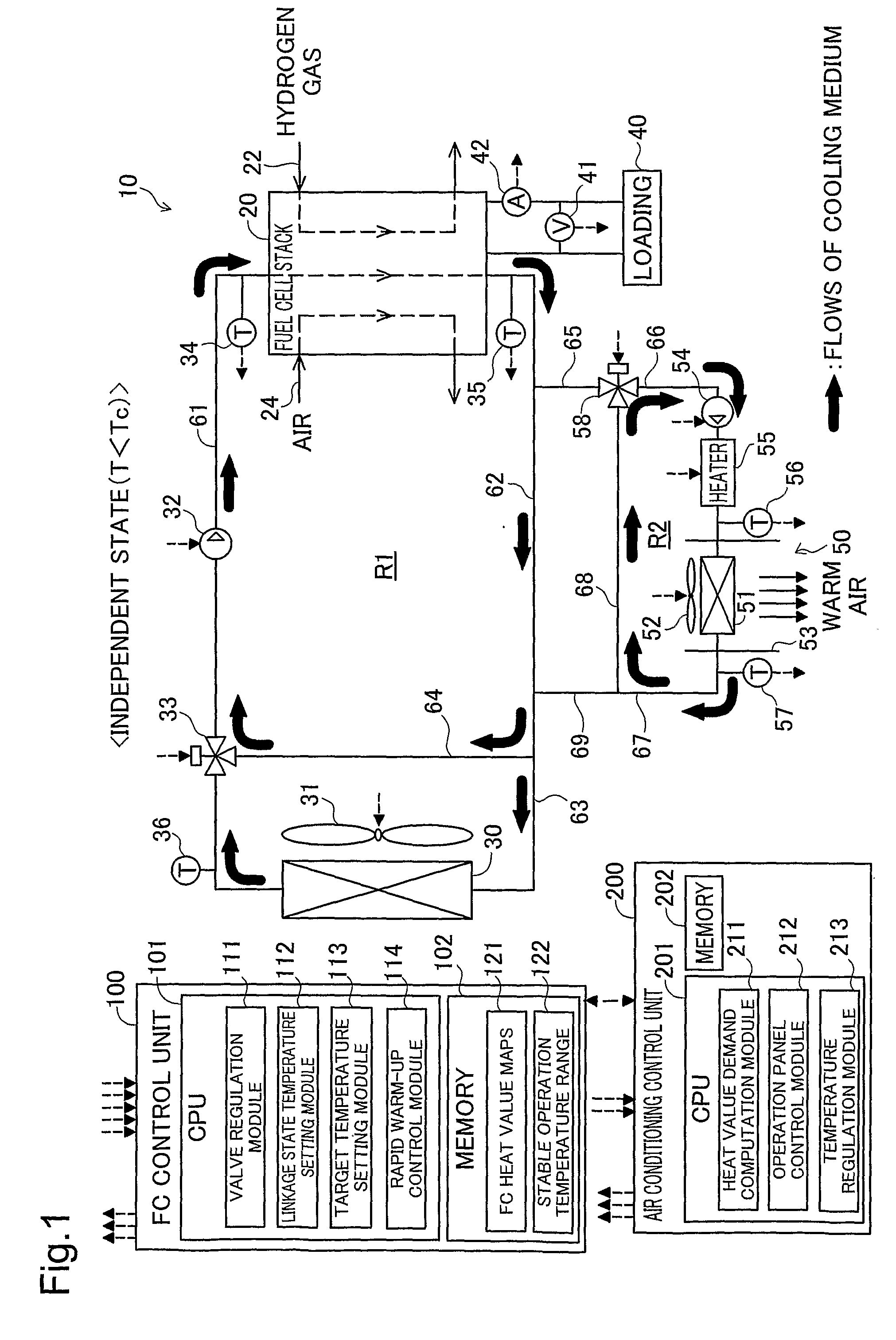
[0034]FIG. 1 is an explanatory view illustrating the schematic configuration of a vehicle control device according to one embodiment of the invention. This vehicle control device 10 is mounted on an electric vehicle that is driven with consumption of electric power generated by fuel cells as the driving power. The vehicle control device 10 includes a fuel cell stack 20 (in the specification hereof, ‘fuel cell’ may be abbreviated as FC), a first medium circuit R1, an air conditioning mechanism 50, a second medium circuit R2, two medium flow paths (fifth and ninth medium flow paths) 65 and 69 arranged to interconnect the two medium circuits R1 and R2, an FC control unit 100, and an air conditioning control unit 200.

[0035]The fuel cell stack 20 of this embodiment is a stack of polymer electrolyte fuel cells obtained by stacking multiple unit cells including membrane electrode assemblies (MEA). The fuel cell stack 20 receives a supply of hydrogen gas...

modified example 1

B1. MODIFIED EXAMPLE 1

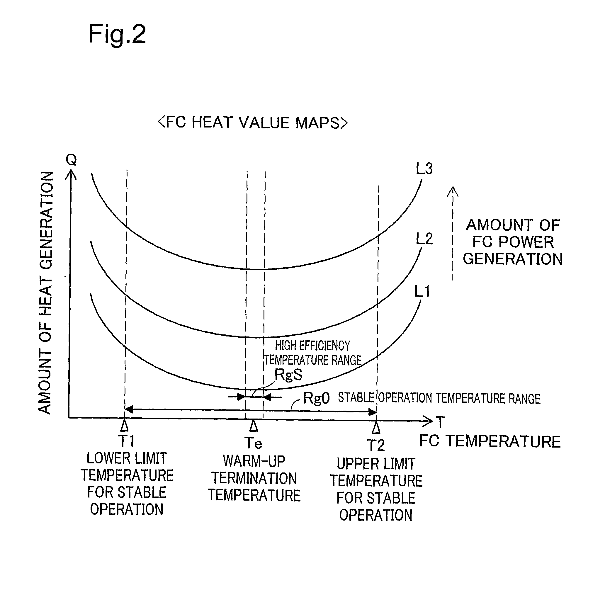
[0104]The temperature setting process of the above embodiment sets the lower limit temperature T1 of the stable operation temperature range Rg0 to the linkage state temperature Tc. Such temperature setting is, however, neither essential nor restrictive. One modified procedure may set the linkage state temperature Tc to any arbitrary temperature in a temperature range specified according to the durability performance of the fuel cell stack 20. In general, in a working environment with a temperature out of a preset temperature range (generally a narrower temperature range than the stable operation temperature range Rg0), the electrolyte membranes and the catalyst layers in the respective unit cells quickly deteriorate, for example, due to the current crowding effect. Setting the linkage state temperature Tc to any arbitrary temperature that is not lower than a lower limit temperature but is not higher than an upper limit temperature of the temperature range speci...

modified example 2

B2. MODIFIED EXAMPLE 2

[0108]The temperature setting process of the above embodiment sets the target temperature Tt to either the upper limit temperature T4 of the below-demand temperature range Rg1 or the upper limit temperature T2 of the stable operation temperature range Rg0. Such temperature setting is, however, neither essential nor restrictive. In the illustrated example of FIG. 4, one modified procedure may set the target temperature Tt to any arbitrary temperature that is higher than the upper limit temperature T4 of the below-demand temperature range Rg1 but is lower than the upper limit temperature T2 of the stable operation temperature range Rg0. In the state where the below-demand temperature range Rg1 is present in the referred heat value map, this modified procedure sets a higher temperature to the target temperature Tt and thereby enables a greater amount of heat to be accumulated in the two medium circuits R1 and R2. This modified arrangement assures a quick response ...


PUM

PropertyMeasurementUnit
linkage state temperatureaaaaaaaaaa
temperatureaaaaaaaaaa
cell voltageaaaaaaaaaa

Abstract

The vehicle control apparatus configured to control a vehicle includes a fuel cell configured to supply electric power to the vehicle; an air conditioning mechanism having a heater core; a first medium circuit; a radiator installed in the first medium circuit; a bypass circuit formed in the first medium circuit to make a bypass flow of the cooling medium bypassing the radiator; a regulation valve installed in the first medium circuit to regulate a ratio of a flow rate of the cooling medium going through the radiator to a flow rate of the cooling medium going through the bypass circuit; a second medium circuit; a cooling medium circulation pump installed in at least one of the first medium circuit and the second medium circuit; a temperature acquisition module; a warm-up controller; and a state switchover structure.

Description

TECHNICAL FIELD[0001]The present invention relates to a technique of utilizing the waste heat of fuel cells for air conditioning.BACKGROUND ART[0002]In a vehicle equipped with fuel cells as an electric power source, several control devices (systems) have been proposed to utilize the waste heat of the fuel cells for heating in air conditioning equipment. One proposed system includes a circuit for making a circulated flow of a cooling medium between the fuel cells and a radiator (for the convenience sake, this circuit is referred to as ‘cooling circuit’ in the following explanation) and a circuit for making a circulated flow of the cooling medium through a heater core used for heating (for the convenience sake, this circuit is referred to as ‘heating circuit’ in the following explanation). When the temperature of the fuel cells is within a specific temperature range with a high power generation efficiency of the fuel cells (for example, a temperature range of 72° C. to 80° C., hereaft...

Claims


Application Information

Patent Timeline
Patent Type & Authority Applications(United States)
IPC IPC(8): B60K11/02G05D23/19B60H1/00B60H1/22B60L11/18H01M8/04H01M8/10
CPCB60H1/00392B60H1/03H01M8/04007H01M8/04701Y02B90/16H01M2250/405Y02E60/50Y02T90/32H01M2250/20Y02B90/10Y02T90/40
Inventor SAKAJO, YUICHISUEMATSU, KEIGONAGANUMA, YOSHIAKIUEHARA, MASANORIKOYAMA, TAKASHI
Owner TOYOTA JIDOSHA KK
Why Eureka
Try Eureka