
LED bulb with heat dissipater

a technology of heat dissipation and led bulb, which is applied in the direction of discharge tube main electrodes, semiconductor devices of light sources, light and heating apparatus, etc., can solve the problems of poor heat dissipation effect, cost increase, and high cost of die casting fins b>20/b>′, so as to reduce manufacturing costs and simplify positioning structure , the effect of reducing the length of the manufacturing process

Inactive Publication Date: 2012-10-04
CHICONY POWER TECH CO LTD
View PDF11 Cites 12 Cited by
  • Summary
  • Abstract
  • Description
  • Claims
  • Application Information

AI Technical Summary

Benefits of technology

[0006]The present invention provides a LED bulb comprising a heat dissipater. By connecting a heat dissipating ring to an outer portion of the fin, not only the heat dissipating area may be increased, but also the heat exchange space in the LED bulb may be increased to allow more incoming air, and thus promote the heat dissipating efficiency.
[0008]The present invention provides an LED bulb comprising a heat dissipater, and the heat dissipater is formed by an aluminum extrusion process so that the duration of manufacturing process can be shortened and the manufacturing cost can be reduced as well.
[0009]The present invention provides a LED bulb comprising a heat dissipater, which include an isolation tube fitted into the hollow tunnel with a simple positioning structure to assemble them together to complete the LED bulb assembly.
[0010]Compared to the conventional art, the LED bulb of the present invention comprises a heat dissipating ring positioned at an outer flange of the fins to increase the heat dissipation area, and the space between the heat dissipating ring, fins and the hollow tunnel can substantially promote the air circulation and allow more incoming air to promote the heat dissipation efficiency. Furthermore, the heat dissipater of the present invention is formed by an aluminum extrusion process, and therefore the manufacturing cost, compared to the conventional molding method, can be substantially reduced. The isolation tube of the present invention extends to receive the power supply or other electronic components to isolate the electronic components and the conducting portion to avoid short circuit from occurring. Moreover, the isolation tube is fitted in the hollow tunnel with the simple structure to achieve the assembly. The heat dissipating ring can also be buckled to the fins, thus the LED bulb assembly can be simplified to increase the practicability of the present invention.

Problems solved by technology

However, this design can only benefit in increasing the heat dissipation area but not the air circulation.
Comparing with the conventional aluminum fins formed in the extrusion or stamping process, the die casting formed fins 20′ are not only more costly but also have poor heat dissipating effect due to the material with the lower heat conductivity.

Method used


Image

  • LED bulb with heat dissipater
  • LED bulb with heat dissipater
  • LED bulb with heat dissipater

Examples


Embodiment Construction

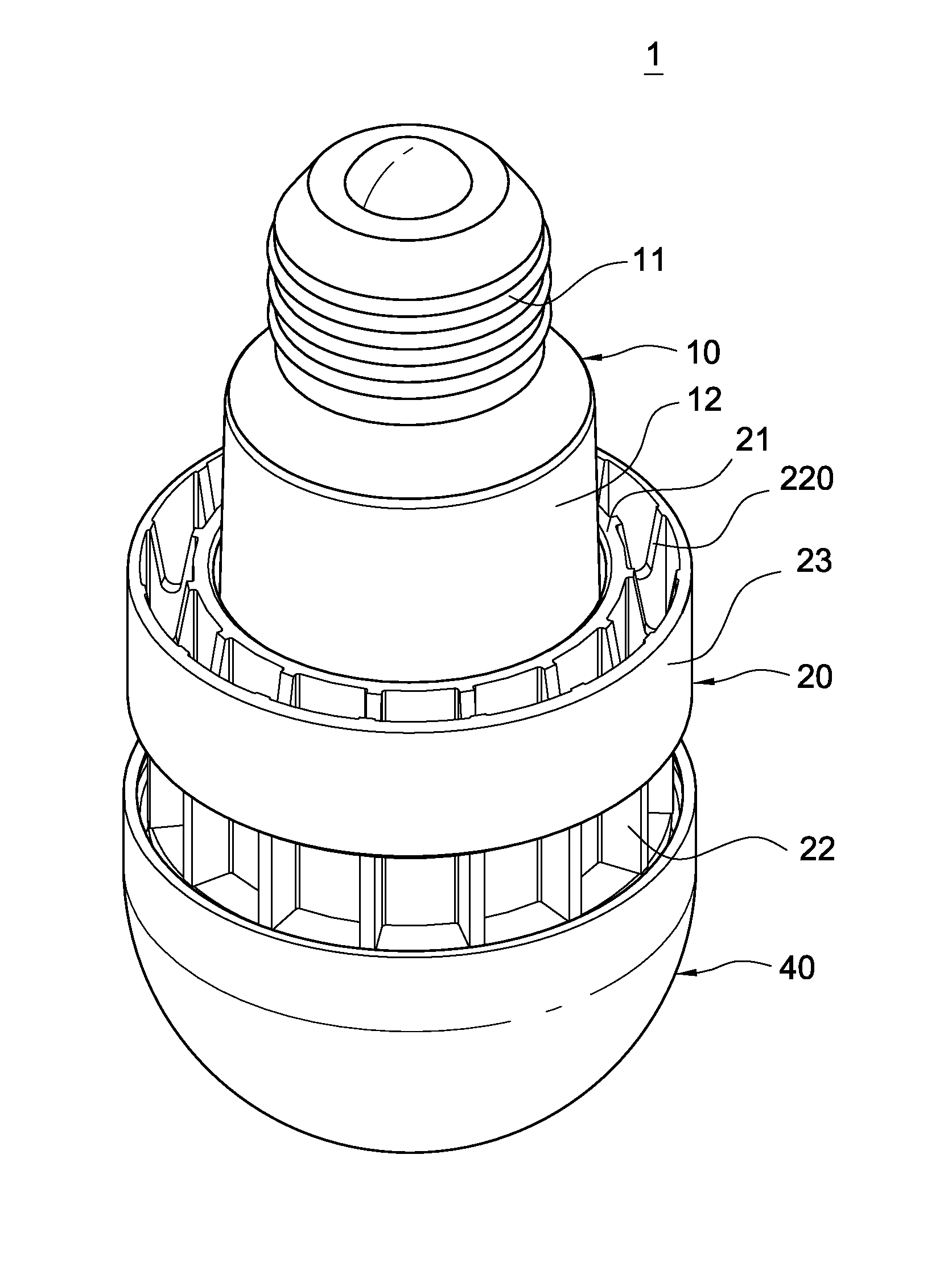
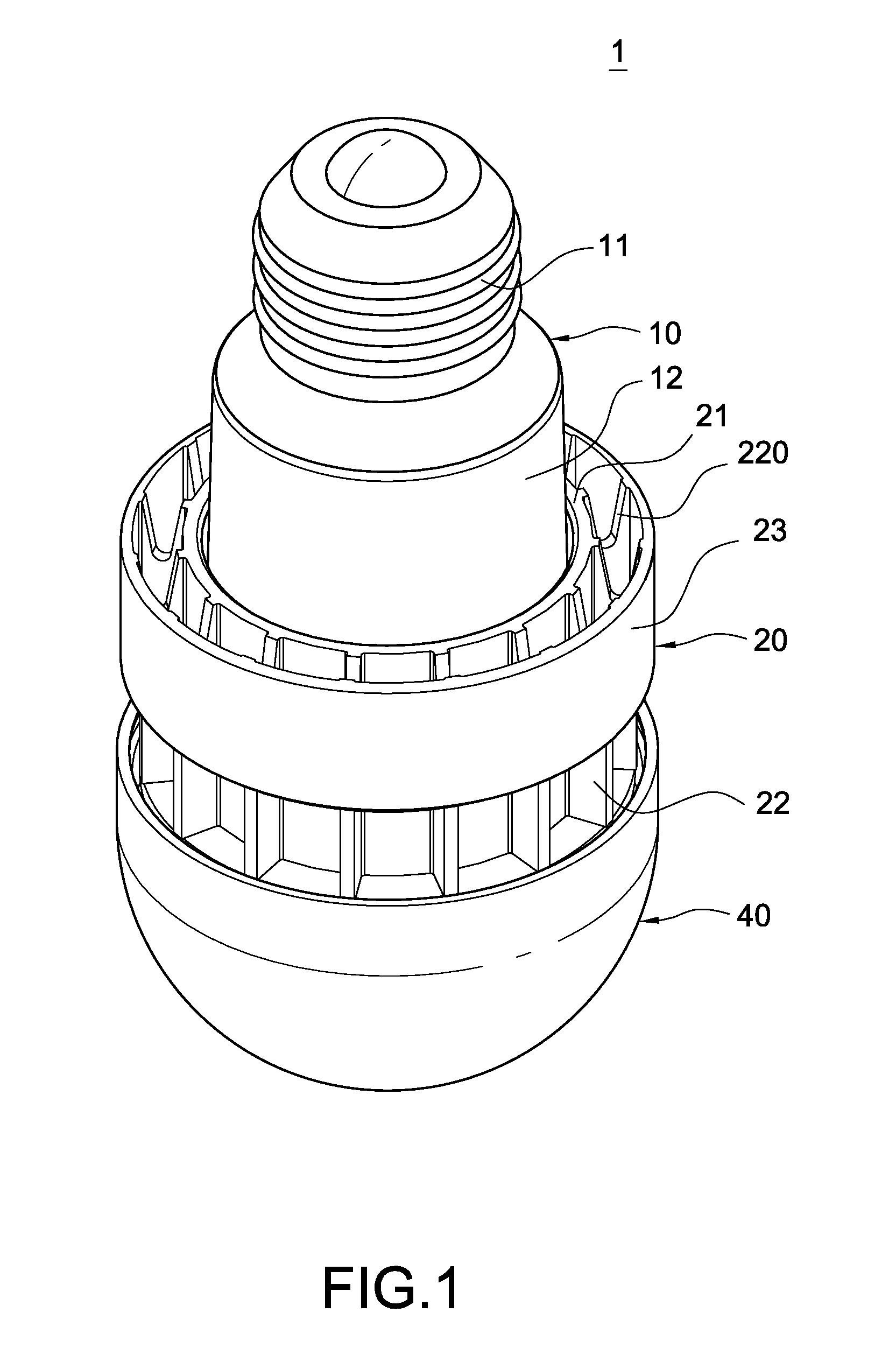
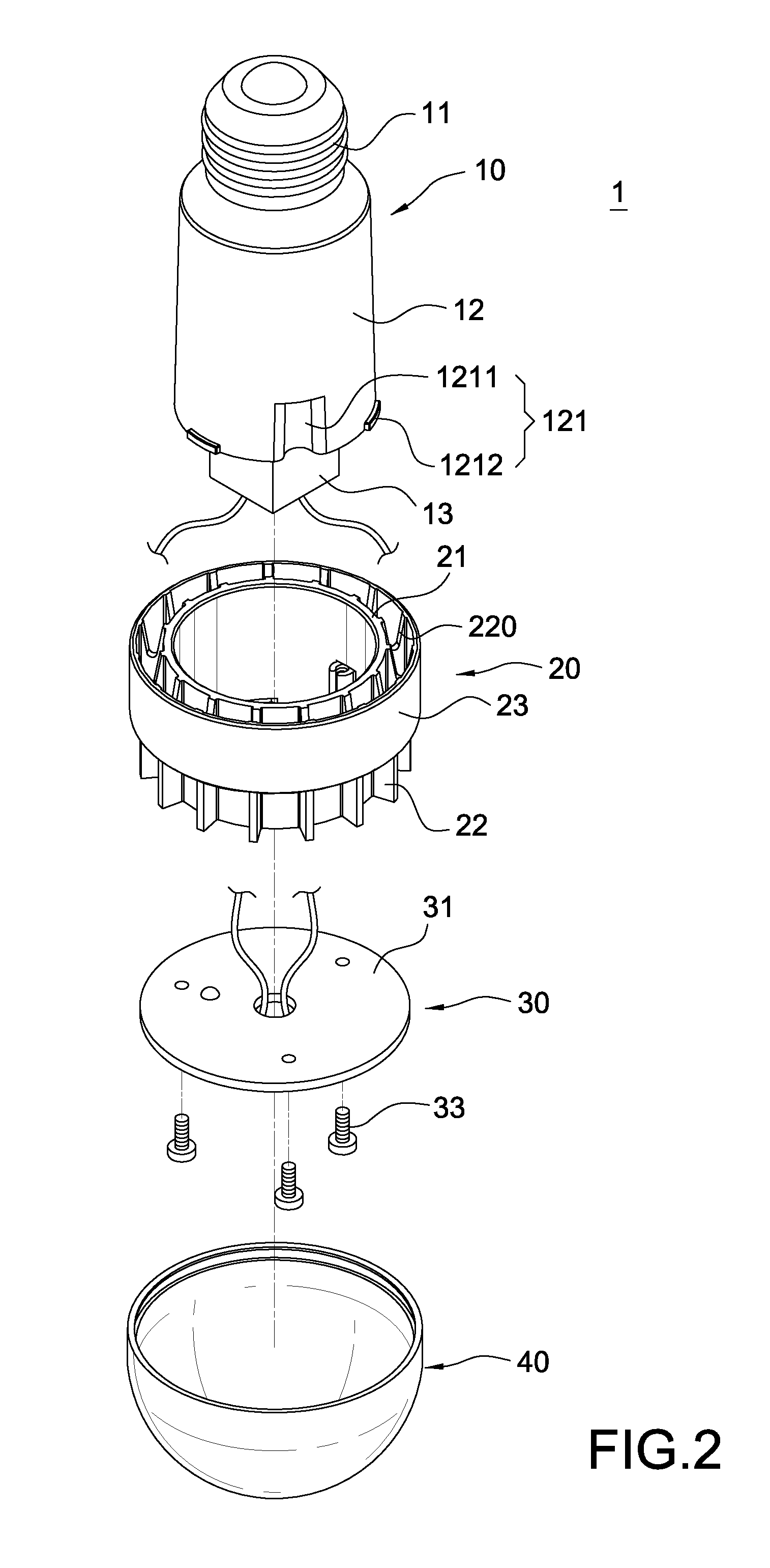
[0024]Referring to FIGS. 1 to 4, a perspective, a perspective view 1, a perspective view and a perspective illustrating another side of a LED bulb comprising a heat dissipater of the present invention. The LED bulb 1 comprises a base 10, a heat dissipater 20, a LED module 30 and a cap 40.

[0025]The base 10 comprises a conducting portion 11 and an isolation tube 12 positioned at the bottom portion of the conducting portion 11. The conducting portion 11 is connected to the external power supply for the LED bulb 1 to operate. The isolation tube 12 receives the electronic components such as the power supply 13. The isolation tube 12 is made of a nonconductive material to insulate those electronic components from the conducting portion 11 to avoid short circuit.

[0026]The heat dissipater 20 is assembled to the isolation tube 12. The isolation tube is manufactured by an aluminum extrusion process. The heat dissipater 20 comprises a hollow tunnel 21, and a plurality of protruded fins 22 exte...


PUM


Abstract

A LED bulb has a heat dissipater. The LED bulb includes a base, a heat dissipater, a LED module and a cap. The base has a conducting portion and an isolation tube positioned at a bottom portion of the conducting portion. The heat dissipater is assembled to the isolation tube. The heat dissipater has a hollow tunnel and a plurality of fins extending perpendicularly and positioned with an interval from one another in a radial fashion. The fins have an outer flange connected to a heat dissipation ring, and the heat dispensing ring is circularly connected to the fins. The LED module has a circuit board fixed to the heat dissipater and a plurality of LED scattered on the circuit board. The cap is assembled to the heat dissipater to house the LED module. The LED bulb increases the air circulation and accordingly promotes the heat dissipation effect.

Description

BACKGROUND[0001]1. Technical Field[0002]The present invention relates to an LED. More particularly, the present invention relates to an LED bulb with a heat dissipater.[0003]2. Related Art[0004]Due to the continuously upgraded functions of the LED, various types of LED bulbs are available on the market to replace the conventional incandescent bulb. Referring to FIG. 9, a LED bulb 1′ of the prior art, because the LED bulb 1′ has a high power LED 10a producing high temperature, therefore, a plurality of fins 20′ are positioned at the housing in order to increase the heat dissipation area. However, this design can only benefit in increasing the heat dissipation area but not the air circulation. To exchange air outside the fins 20′ without air circulation thus the effect of heat dispensing is limited.[0005]Furthermore, the fins 20′ of the LED 10′ are mostly formed by the die casting process. Comparing with the conventional aluminum fins formed in the extrusion or stamping process, the d...

Claims


Application Information

Patent Timeline
Patent Type & Authority Applications(United States)
IPC IPC(8): H01J61/52
CPCF21V29/004F21V3/00F21K9/135F21V19/0055F21V29/83F21V23/004F21Y2101/02F21Y2105/001F21V29/773F21V23/002F21K9/00F21V23/006F21K9/232F21K9/238F21Y2105/10F21Y2115/10
Inventor LAI, CHYI-LANG
Owner CHICONY POWER TECH CO LTD
Learn More