System and method for identifying a spatial relationship for use in calibrating accelerometer data

a technology of spatial relationship and accelerometer, which is applied in the field of system and method for identifying spatial relationship for use in calibrating accelerometer data, can solve the problems of inaccurate mounting of accelerometer, potential meaninglessness of accelerometer data output, and difficulty in accurately mounting the accelerometer. to achieve the effect of improving accuracy

Active Publication Date: 2012-10-04
TRIMBLE NAVIGATION LTD
View PDF3 Cites 45 Cited by
  • Summary
  • Abstract
  • Description
  • Claims
  • Application Information

AI Technical Summary

Benefits of technology

[0023]To improve accuracy, an average of the second set of vector data may be used. A filter, for example a leaky integrator, may be used to calculate this second average. The second average may be a shorter term average (compared to the first average), consequently the period over which samples are taken may be shorter. In addition, the vehicle may ‘dip’ under braking,

Problems solved by technology

It is unlikely that the accelerometer will be accurately mounted in the vehicle, this may be due to space/fixing constraints (that is the unit containing the accelerometer can only be mounted in one orientation) or may be simply d

Method used


Image

  • System and method for identifying a spatial relationship for use in calibrating accelerometer data
  • System and method for identifying a spatial relationship for use in calibrating accelerometer data
  • System and method for identifying a spatial relationship for use in calibrating accelerometer data

Examples


Embodiment Construction

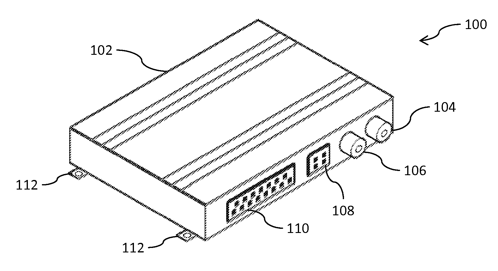
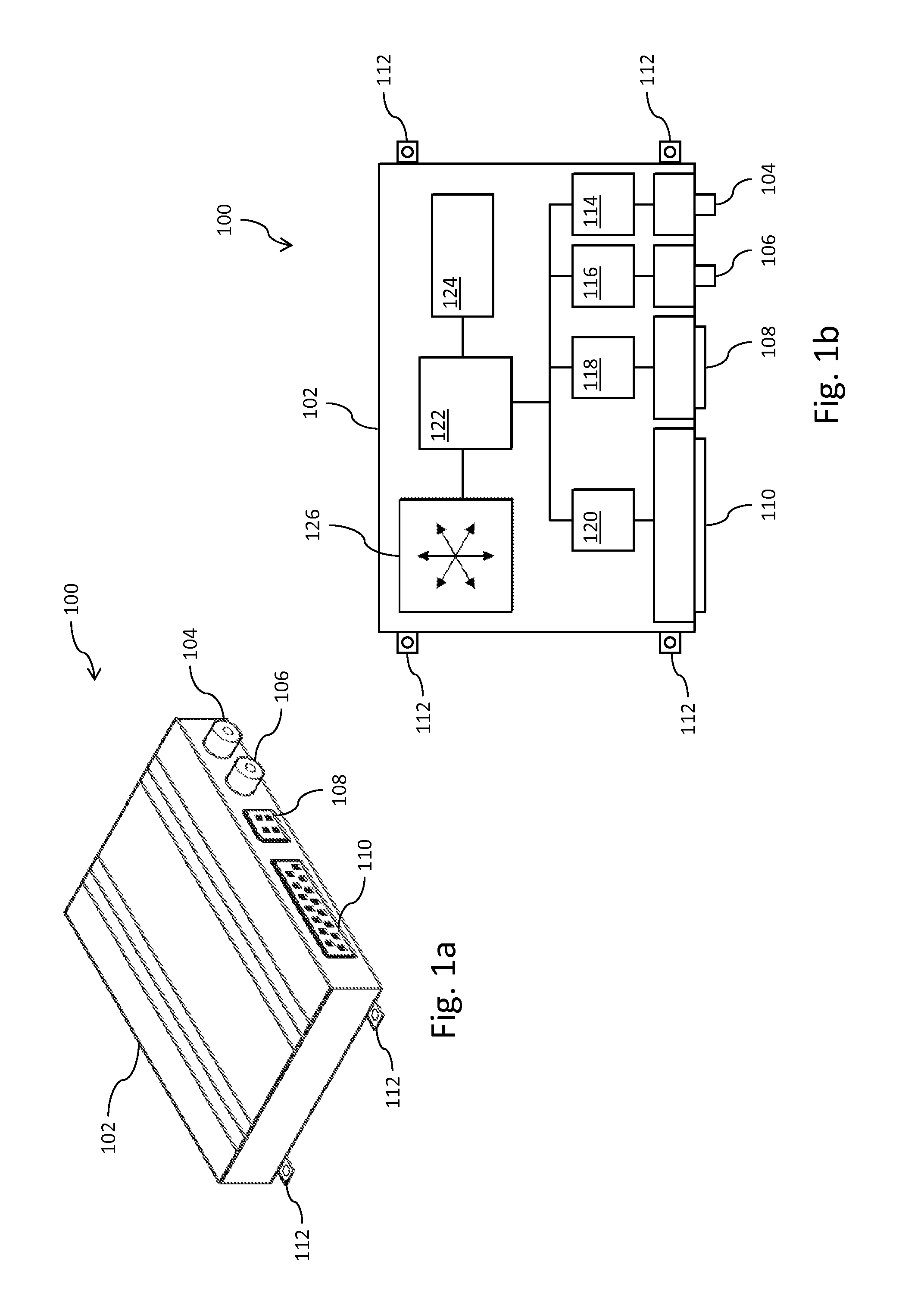
[0046]FIG. 1 shows a perspective view of a telematics unit 100 according to an embodiment of the invention. The telematics unit 100 has a case 102, on the side of which are a number of connectors 104, 106, 108 and 110.

[0047]Of these connectors, a GPS antenna connector 104 and a mobile communications antenna connector 106 enable the telematics unit 100 to be connected to external antennae. Consequently the telematics unit 100 can be mounted in a position in the vehicle, for example in the engine bay, where normally such antenna would be ineffective due to the quantity of metal blocking the signal. The connected antennae may then be mounted in the vehicle in a position where the signal strength is sufficient for effective operation.

[0048]User interface connector 108 is provided to connect the telematics unit 100 to a user interface unit (not shown). The user interface unit can be mounted in the cab of the vehicle, and be used, for example, to allow a driver of vehicle login or to prov...


PUM


Abstract

Methods and systems for identifying a spatial relationship between a frame of reference associated with an accelerometer mounted in a vehicle and a frame of reference associated with the vehicle Accelerometer data is received from an accelerometer and vehicle data is received from a vehicle network of the vehicle, a long term average of the accelerometer data is used to determine the direction of gravity in the frame of reference of the vehicle. In addition the vehicle date is used to determine changes in speed of the vehicle, and thus to determine the direction of the longitudinal axis of the vehicle in the frame of reference of the vehicle. From these determined directions, the spatial relationship between the frames of reference may be determined.

Description

FIELD OF THE INVENTION[0001]The present invention relates to systems and methods for identifying a spatial relationship between a first and a second frame of reference for use in calibrating accelerometer data and in particular when the first frame of reference is associated with an accelerometer mounted in a vehicle and the second frame of reference is associated with the vehicle.BACKGROUND[0002]Telematics units are known and may be used to track and monitor vehicles such as cars, motorcycles, vans and trucks. The telematics unit is mounted in the vehicle and gathers information about the status of the vehicle. The telematics unit may then either store the information for later retrieval, or report the information to a remote monitoring station using a mobile communications network.[0003]An exemplary telematics unit may contain a Global Positioning System (GPS) unit, a connection to a vehicle network (such as a Controller-Area Network or CAN) and a connection to a user interface. T...

Claims


Application Information

Patent Timeline
IPC IPC(8): G06F7/00
CPCG07C5/085
Inventor HARVIE, RICHARD
Owner TRIMBLE NAVIGATION LTD
Why Eureka
Try Eureka