Ct system for use in multi-modality imaging system

a multi-modality imaging and computed tomography technology, applied in tomography, instruments, nuclear engineering, etc., can solve the problems of increasing the cost of constructing a facility for housing such a system, reducing the footprint of the facility, and reducing the cost of constructing a facility for such a system

Inactive Publication Date: 2012-10-11
GENERAL ELECTRIC CO
View PDF7 Cites 118 Cited by
  • Summary
  • Abstract
  • Description
  • Claims
  • Application Information

AI Technical Summary

Benefits of technology

[0006]The present invention provides for a combined SPECT / CT imaging system that addresses problems that may be found in existing systems. In one embodiment, the present SPECT / CT system utilizes a distinct CT subsystem in which the CT detector components rotate independent of the gamma detectors of the SPECT subsystem and, in one implementation rotate at rotation speed greater than 30 RPM, and preferably about 60 rotations per minute (RPM) or above, typically the same or faster than the corresponding gamma detection components. Further, in one such implementation, the CT subsystem operates at a low dose (i.e., at a limited mAs and / or with a suitable bowtie filter). In embodiments where the CT subsystem operates at a low dose, the SPECT / CT system and / or the surrounding environment or room may use no or reduced shielding or radiation protection, in contrast to the higher level of shielding and / or protection that is typically associated with higher dose (e.g., diagnostic) CT systems. Further, the CT subsystem of the present SPECT / CT system may have a reduced footprint with respect to other conventional SPECT / CT systems.

Problems solved by technology

However, due to differences in the manner in which SPECT and CT systems operate, e.g., the physical phenomena measured and the manner in which measurement is accomplished, it may be difficult to design a combined modality imaging system that provides the desired functionality and performance with respect to each different imaging modality.
To meet these requirements, the walls of a room housing such a system may be shielded (such as with lead plating having a thickness of 2 mm or more), which can add substantially to the cost of constructing a facility for housing such a system.
Further, use of such shielding can environmental and recycling issues due to the presence of lead.

Method used


Image

  • Ct system for use in multi-modality imaging system
  • Ct system for use in multi-modality imaging system
  • Ct system for use in multi-modality imaging system

Examples


Embodiment Construction

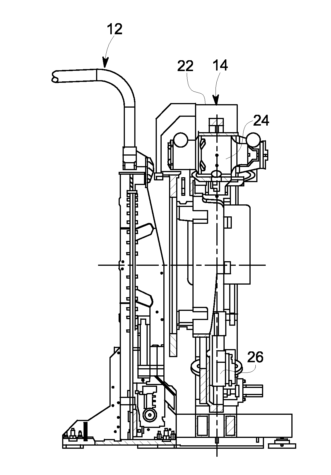
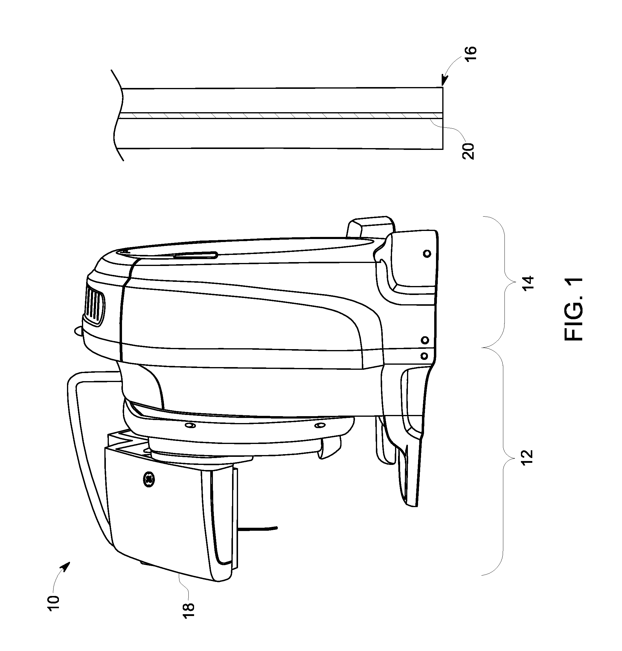
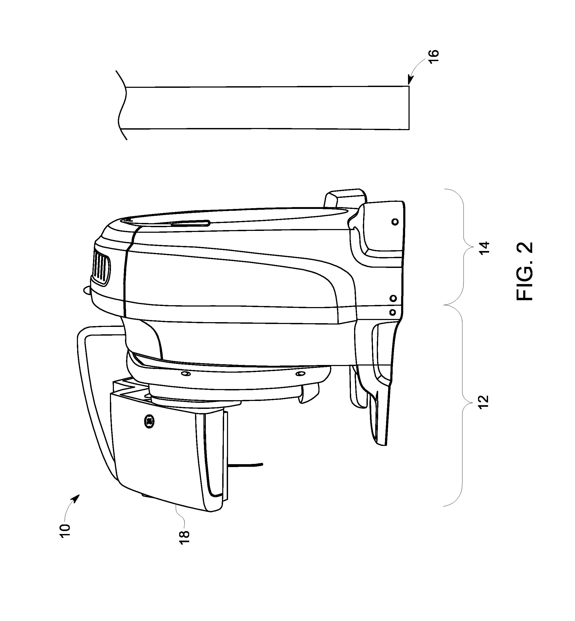
[0015]A diagrammatic representation of an exemplary SPECT / CT imaging system is shown in FIG. 1. The multi-modality system, designated generally by the reference numeral 10, is designed to acquire both structural (e.g., CT) and functional (e.g., SPECT) image data during an imaging session. In the depicted embodiment, the multi-modality imaging system 10 includes a SPECT subsystem 12 and a CT subsystem 14. As will be appreciated, though a SPECT imaging modality is primarily discussed herein, other nuclear medicine imaging modalities (such as positron emission tomography (PET)) may also be used to provide functional imaging in conjunction with the CT imaging subsystem discussed herein. It also should be noted that the rotating, dual-detector, L-mode gamma camera depicted herein is to be viewed as a non-limiting example. Other gamma camera configurations such as fixed multiple pinhole configurations or swiveling heads may be used within the scope of the invention. Additionally, the rela...


PUM


Abstract

A computed tomography (CT) imaging system is disclosed. The CT imaging system may be used in a multi-modality imaging context or other context. In one embodiment, the CT imaging system provides for both fast rotation of the rotating X-ray source and detection components and low dose of X-rays generated by the source providing several clinical and economic benefits such as low dose and sufficient image quality and no or insignificant investment in room shielding associated with diagnostic CT dose.

Description

BACKGROUND OF THE INVENTION[0001]The subject matter disclosed herein relates to a multi-modality imaging system employing computed tomography (CT) and, more particularly to single photon emission computed tomography (SPECT) or positron emission tomography (PET) systems combined as part of a SPECT / CT or PET / CT system.[0002]Non-invasive imaging broadly encompasses techniques for generating images of the internal structures or regions of a person that are otherwise inaccessible for visual inspection. One of the best known uses of non-invasive imaging is in the medical arts where these techniques are used to generate images of organs and / or bones inside a patient which would otherwise not be visible. One class of medical non-invasive imaging modalities is based on the generation of structural images of internal structures which depict the physical arrangement of the imaged region. One example of such a modality is computed tomography (CT), which is based on the differential transmission...

Claims


Application Information

Patent Timeline
Patent Type & Authority Applications(United States)
IPC IPC(8): A61B6/03G01T1/166
CPCA61B6/032A61B6/037A61B6/5235A61B6/12A61B6/4417A61B6/107
Inventor ZINGERMAN, YULIM
Owner GENERAL ELECTRIC CO
Why Eureka
Try Eureka