Adaptive phase contrast microscope

a phase contrast microscope and phase contrast technology, applied in the field of optical microscopes, can solve the problems of affecting the image quality of the image, the inability to adjust the phase ring, and the inability to see the live cell, so as to improve the image quality, improve the viewing area, and prolong the time

Inactive Publication Date: 2012-10-11
KAIROS INSTR
View PDF7 Cites 52 Cited by
  • Summary
  • Abstract
  • Description
  • Claims
  • Application Information

AI Technical Summary

Benefits of technology

[0016]According to a third aspect, the present invention includes a second camera mounted on the eyepiece, with the Bertrand lens in place. This image is used to adjust the light pattern from the visible LCD, to align the light and dark rings and to compensate for a meniscus that is off-center from the viewing area in a micro plate well. The pattern in the visible LCD is shifted and the pattern changed to an oval, for example, allowing for a greater region of viewing in the micro plate.
[0017]According to a fourth aspect, implementation of the invention involves adjusting the phase ring by using image processing techniques, looking for peak intensity in the image based on a pixel contribution to the phase contrast image. This is accomplished by sending a sequence of patterns through the sample and processing the images to develop the best pattern for a final phase image. The method will work with or without the use of the Bertrand image. Since this is a dynamic adjustment of the phase ring, changes in objectives or changes in the plate or the fluid height, as well as changes in the fluid viscosity can all be corrected. As the cells in the well change shape and density, changes in the visible condenser annulus are adjusted and the intensity of the light adjusted, typically brighter, to provide an improved image over a longer period of time.
[0018]According to a fifth aspect, the invention allows for the wavelength used to image the cells and view cells to be adjustable. Many cameras are sensitive to certain wavelengths, as well as the human eye. The transmitted light through the LCD can be adjusted to transmit a specific band of light, taking into account the improved imaging capabilities of the camera. The wavelength of the light also has an effect on the cells. Live cells are more sensitive to shorter wavelengths, and in some cases, the lens in the microscope can be affected by the wavelength as well. Small changes in focus, due to changes in the wavelength are possible with this system.

Problems solved by technology

Live cells are transparent and difficult to see without a means to enhance the image.
With the sample in the light path, the transparent cell causes the light ring to be refracted, resulting in misalignment with the dark phase ring.
This misalignment causes constructive interference, producing a bright area.
In the case where one is observing live cells under a liquid, the light is distorted by the liquid before reaching the cell and phase imaging is greatly compromised.
In the middle of the well, a reduced but useable version of phase imaging is possible, however, care must be taken to ensure that the image is taken from the middle of the well, otherwise, the image is not useable.
However, during the course of observation of the live cells, the distribution of the cells may change causing one to move away from the center of the well.
Thus, one can only get minimal phase at the very center of the well.
Hence, use of these micro plates having a higher number of wells would be difficult, if not impossible.
However, the rotation of this polarizing plate requires a separate mechanical member.

Method used


Image

  • Adaptive phase contrast microscope
  • Adaptive phase contrast microscope
  • Adaptive phase contrast microscope

Examples


Embodiment Construction

[0035]For purposes of the description hereinafter, the terms “upper”, “lower”, “right”, “left”, “vertical”, “horizontal”, “top”, “bottom”, “lateral”, “longitudinal”, and derivatives thereof, shall relate to the invention as it is oriented in the drawing figures. However, it is to be understood that the invention may assume various alternative variations, except where expressly specified to the contrary. It is also to be understood that the specific devices illustrated in the attached drawings, and described in the following specification, are simply exemplary embodiments of the invention. Hence, specific dimensions and other physical characteristics related to the embodiments disclosed herein are not to be considered as limiting.

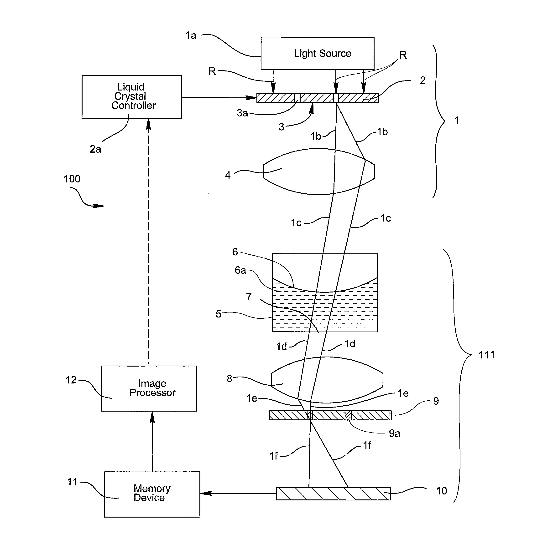
[0036]Reference is now made to FIG. 1 which is a schematic side view showing an embodiment of the phase contrast microscope, generally indicated as 100, according to one arrangement of the invention. The inverted microscope includes an illuminating optical s...


PUM

PropertyMeasurementUnit
viscosityaaaaaaaaaa
brightnessaaaaaaaaaa
fluorescentaaaaaaaaaa

Abstract

An optical microscope is provided with an adjustable optical phase ring. The adjustable ring provides a way to compensate for distortion in the visible phase ring before the light reaches the sample. In an inverted microscope, when observing transparent cells under a liquid, the visible light phase ring is distorted. By the use of a Liquid Crystal Display (LCD) in place of a fixed ring, the projected ring is adjusted to realign the light and produce phase. In a typical micro plate, the meniscus formed produces a lens effect that is realigned by providing changes in the position and pattern, to allow phase imaging over a wider portion of the well. The realignment of the ring can be manual or automated and can be dynamically adjusted based upon an observed image of the sample.

Description

CROSS-REFERENCE TO RELATED APPLICATION[0001]This application claims priority to U.S. Provisional Patent Application No. 61 / 473,252 filed Apr. 8, 2011, which is incorporated herein by reference.BACKGROUND OF THE INVENTION[0002]1. Field of the Invention[0003]The present invention is directed to an optical microscope having an adjustable optical condenser annulus and, more particularly, to a phase contrast or inverted microscope using an electrical device to construct a dynamically adjustable visible condenser annulus for viewing transparent living cells under a liquid.[0004]2. Description of Related Art[0005]The present invention relates to a phase contrast microscope for viewing transparent living cells under a liquid. In this configuration of the microscope, called an inverted microscope, the samples of cells are placed in a micro plate under a liquid. Living cells are placed on a plate on the microscope and a light from above the well illuminates the sample. The cells are typically...

Claims


Application Information

Patent Timeline
Patent Type & Authority Applications(United States)
IPC IPC(8): G02B21/14H04N7/18G02F1/13
CPCG02B21/14
Inventor KOEBLER, DOUGLAS J.BAHNSON, ALFRED BLALOCK
Owner KAIROS INSTR
Why Eureka
Try Eureka