
Aftertreatment system and control strategy for internal combustion engine

Active Publication Date: 2012-10-18
MITSUBISHI HEAVY IND ENGINE & TURBOCHARGER LTD
View PDF5 Cites 12 Cited by
  • Summary
  • Abstract
  • Description
  • Claims
  • Application Information

AI Technical Summary

Benefits of technology

[0050]The method according to the present invention is a control strategy of aftertreatment system for an internal combustion engine, including a collecting step of collecting particulate matter contained in an exhaust gas discharged from the internal combustion engine in a filter, and a active regeneration step of post-injecting a fuel to heat the exhaust gas to a combustion temperature of the particulate matter in a diesel oxidation catalyst, whereby the particulate matter collected in the filter is burned and removed by the heated exhaust gas, the control strategy including: a first step of detecting an exhaust gas temperature at an inlet of the filter and determining whether or not a DPF abnormal combustion causing operation, in which the internal combustion engine shifts from a high rotation or high load operating condition to a low rotation, low load operating condition including an idling condition within a set time, has occurred during the active regeneration step; a second step of increasing an exhaust gas flow by performing at least one operation from among fully opening a throttle valve provided in an intake pipe or an exhaust pipe and not reducing a rotation speed during a low load operation to or below a set value when, in the first step, the exhaust gas temperature at the inlet of the filter is determined to equal or exceed the combustion temperature of the particulate matter and the DPF abnormal combustion causing operation is determined to have occurred; and a third step that is performed in parallel with the second step to reduce a combustion speed of the particulate matter by reducing an oxygen concentration of the filter while continuing the post-injection as is. Hence, an abnormal temperature increase caused by abnormal combustion in the DPF can be eliminated early, and as a result, breakage of the DPF due to heat-generated melting and cracks can be prevented and thermal deterioration of the catalyst coated on the DPF can be prevented.
[0051]Further, the occurrence of abnormal combustion in the DPF can be predicted with a considerable degree of accuracy, and therefore unnecessary control is not performed when abnormal combustion has not occurred in the DPF. As a result, the thermal efficiency of the internal combustion engine does not decrease. Moreover, the post-injection is continued as is in the third step, and therefore the active regeneration step is not interrupted and restarted repeatedly. As a result, the DPF can be maintained at a constant temperature enabling combustion and removal of the PM, and therefore the thermal efficiency of the internal combustion engine does not decrease. Furthermore, since the post-injection is continued as is, reductions can be achieved in the oil dilution that tends to occur during the active regeneration step and the amount of consumed fuel.
[0052]The device according to the present invention is an aftertreatment system for an internal combustion engine, in which a diesel oxidation catalyst and a filter are provided in an exhaust pipe of the internal combustion engine, particulate matter contained in an exhaust gas is collected in the filter, and a fuel is post-injected to heat the exhaust gas to a combustion temperature of the particulate matter in the diesel oxidation catalyst, whereby the particulate matter collected in the filter is burned and removed by the heated exhaust gas, the aftertreatment system including: a throttle valve provided in an intake pipe or the exhaust pipe; a temperature sensor that detects an exhaust gas temperature at an inlet of the filter; a DPF abnormal combustion determination unit that determines whether or not a DPF abnormal combustion causing operation, in which the internal combustion engine shifts from a high rotation or high load operating condition to a low rotation, low load operating condition including an idling condition within a set time, has occurred; and a controller that performs control to increase an exhaust gas flow while continuing the post-injection as is by performing at least one operation from among fully opening the throttle valve and not reducing a rotation speed during a low load operation to or below a set value when, in a active regeneration step of burning and removing the particulate matter collected in the filter, the exhaust gas temperature at the inlet of the filter is determined to equal or exceed the combustion temperature of the particulate matter and the DPF abnormal combustion determination unit determines that the DPF abnormal combustion causing operation has occurred. Hence, similar actions and effects to the method according to the present invention can be obtained.

Problems solved by technology

As shown in FIG. 9, however, when the diesel engine shifts from a normal operation to a low rotation, low load operation such as an idling operation during the active regeneration process of the DPF, the PM collected in the DPF may burn abnormally such that the DPF is abnormally heated.
Therefore, as shown in FIG. 9, the internal temperature of the DPF device may increase abnormally, and as a result, the DPF may break due to heat-generated melting or cracks.
Further, in a case where a catalyst is coated on the DPF, thermal deterioration may occur in the catalyst.

Method used


Image

  • Aftertreatment system and control strategy for internal combustion engine
  • Aftertreatment system and control strategy for internal combustion engine
  • Aftertreatment system and control strategy for internal combustion engine

Examples


first embodiment

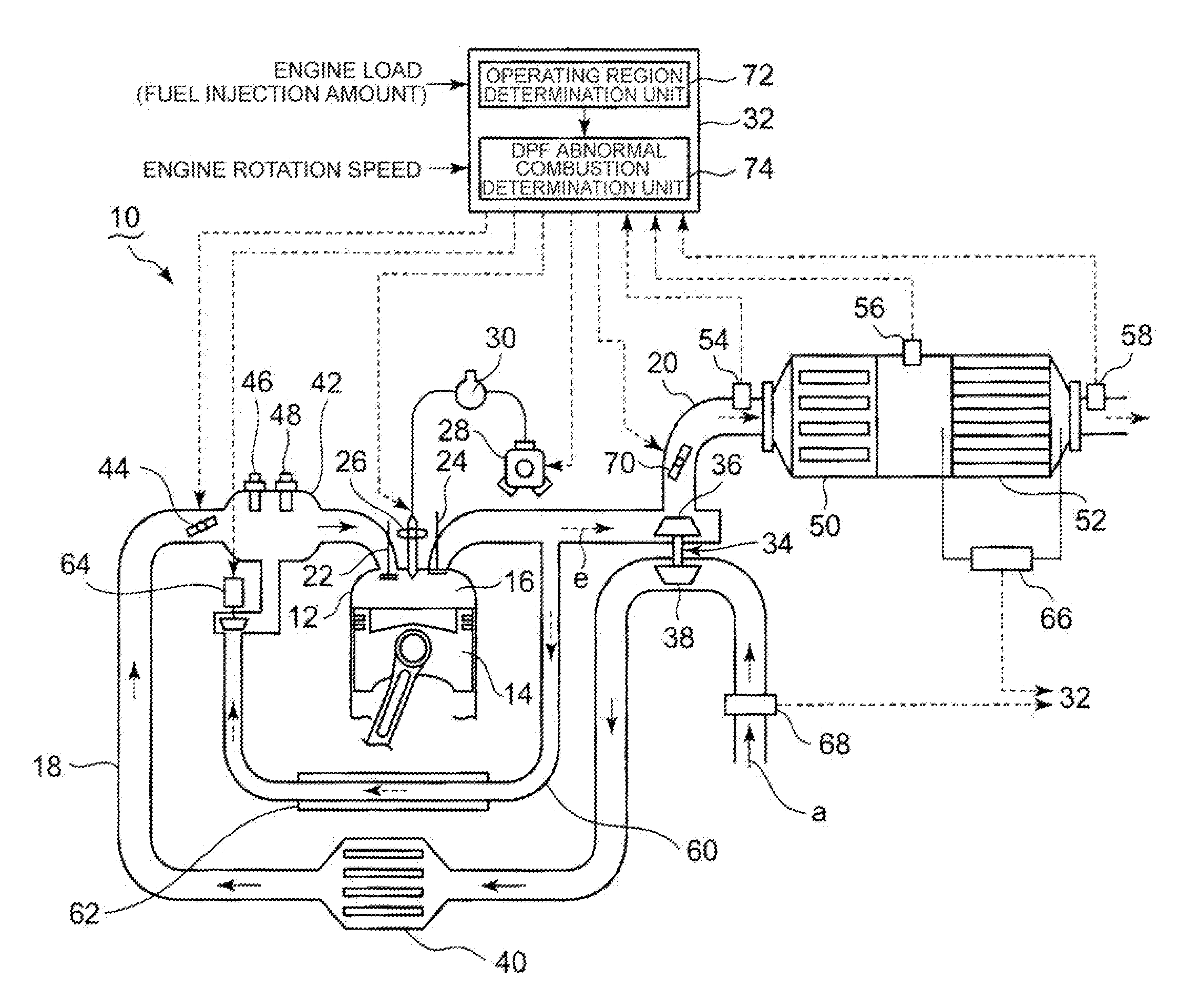
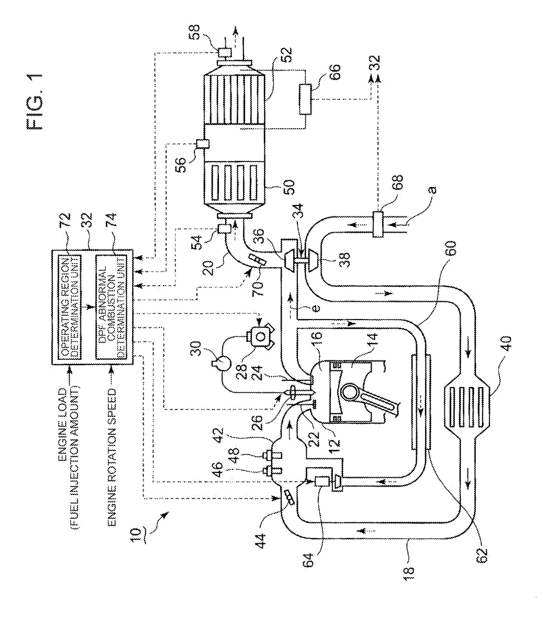
[0063]A first embodiment in which the method and device according to the present invention are applied to a diesel engine will now be described using FIGS. 1 to 3. In FIG. 1, a piston 14 is built into an interior of a combustion cylinder 12 of a diesel engine 10, and a combustion chamber 16 is formed above the piston 14. An intake pipe 18 and an exhaust pipe 20 are connected to a cylinder head of the combustion cylinder 12. An intake valve 22 and an exhaust valve 24 are provided in respective connecting portions between the intake pipe 18 and exhaust pipe 20 and the combustion cylinder 12.

[0064]An injector 26 that injects fuel into the combustion chamber 16 is provided in a central upper portion of the cylinder head. Fuel such as light oil is supplied to the injector 26 at high pressure from an injector pump 28 via a common rail (an accumulator) 30, and the injector 26 injects the fuel into the combustion chamber 16. An injection timing and an injection amount of the fuel are contro...

second embodiment

[0091]Next, a second embodiment of the method and device according to the present invention will be described using FIGS. 5 and 6. The configuration of the diesel engine 10 according to this embodiment is identical to the first embodiment. As shown in FIG. 5, in the control procedures according to this embodiment, Steps 24, 25, and 26 differ from the first embodiment, but all other steps are identical to the first embodiment.

[0092]In Step 25 of this embodiment, an accumulated amount of PM collected in the DPF device 52 is estimated. As regards an estimation method, the collected PM amount can be determined by determining the fuel injection amount and a fuel combustion amount input into the ECU 32 as functions of the exhaust gas temperature, and subtracting the fuel combustion amount from the fuel injection amount. Alternatively, the accumulated PM amount can be determined from the differential pressure of the exhaust gas to the front and rear of the DPF device 52, which is determine...


PUM


Abstract

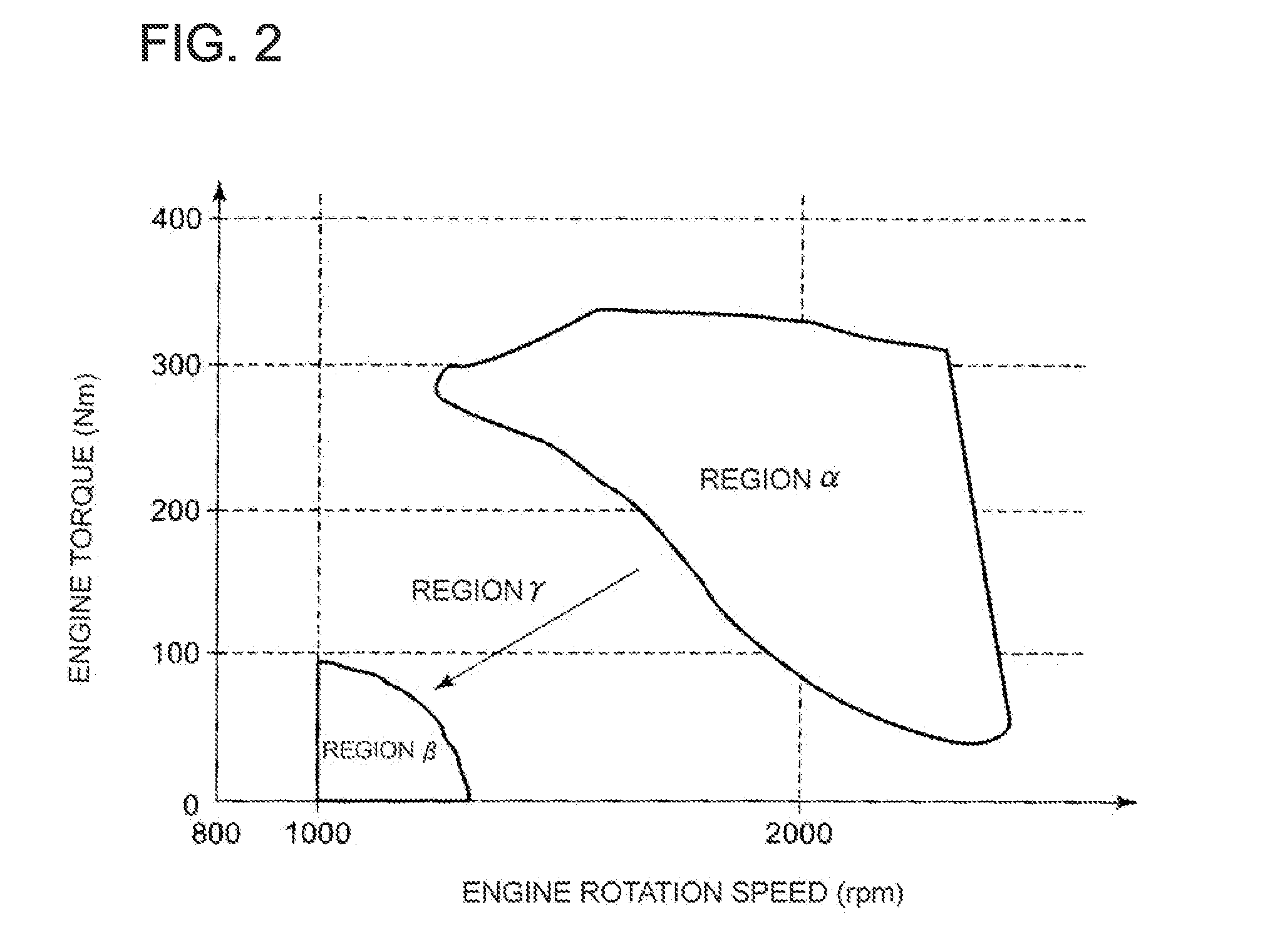
In an exhaust gas treatment device in which a diesel oxidation catalyst and a DPF are provided in an exhaust pipe of an internal combustion engine, abnormal combustion in the DPF, occurring when the internal combustion engine varies from a high load condition to a low load condition, poses a problem. To solve this problem, in the present invention, a DPF abnormal combustion causing operation is determined to have occurred when the internal combustion engine shifts from a high rotation or high load operation region α to a low rotation, low load operation region β within a set time T1. When it is determined that a DPF abnormal combustion causing operation has occurred, abnormal combustion of PM collected in the DPF is suppressed by fully opening an intake throttle valve 44 in order to increase an exhaust gas flow so that heat is removed by sensible heat of the exhaust gas, thereby cooling a DPF device 52, and continuing a late post-injection in order to reduce an oxygen concentration of the DPF. As a result, an abnormal temperature increase in the DPF device 52 can be suppressed early.

Description

TECHNICAL FIELD[0001]The present invention relates to an aftertreatment system and control strategy in which a diesel oxidation catalyst and a filter that collects particulate matter are provided in an exhaust pipe of an internal combustion engine, and more particularly a diesel engine.BACKGROUND ART[0002]According to exhaust gas regulations for diesel engines, reducing particulate matter (“PM” hereafter) is equally as important as reducing NOx. A PM collecting unit using a filter known as a DPF (Diesel Particulate Filter) is known to be effective in removing PM from exhaust gas.[0003]In an operating condition where an exhaust gas temperature is low, PM gathers in the DPF continuously, and therefore active regeneration for removing the PM through combustion must be performed on the DPF by forcibly increasing the temperature of the exhaust gas.[0004]This active regeneration process will now be described using FIGS. 7 and 8. A diesel oxidation catalyst (DOC) is provided in an exhaust ...

Claims


Application Information

Patent Timeline
IPC IPC(8): F01N11/00F01N3/025
CPCF01N3/0235Y02T10/42F02B29/0406F02D9/04F02D41/0002F02D41/0235F02D41/025F02D41/029F02D41/405F02D2041/0022F02D2041/0265F02D2200/0802F02D2200/0812F02M25/0707F02M25/0713F02M25/0727F01N3/035F01N3/0253F01N9/002F01N2240/36F01N2430/08F01N2560/06F01N2900/08F01N2900/1404F02D31/001F01N13/009F02M26/05F02M26/10F02M26/23Y02T10/40F01N3/02F01N3/023F01N9/00
Inventor MASUDA, TOMOTSUGUTAKAYANAGI, KOOKUDA, KEISUKENISHIZAWA, KAZUKI
Owner MITSUBISHI HEAVY IND ENGINE & TURBOCHARGER LTD
Learn More