Driving device

a technology of driving device and internal combustion engine, which is applied in the direction of combination engines, machines/engines, mechanical apparatus, etc., can solve the problems that generated steam can at least supplement, and achieve the effects of improving the degree of filling, or volumetric efficiency, and increasing the efficiency of the internal combustion engin

Inactive Publication Date: 2012-10-18
ROBERT BOSCH GMBH
View PDF3 Cites 14 Cited by
  • Summary
  • Abstract
  • Description
  • Claims
  • Application Information

AI Technical Summary

Benefits of technology

[0004]In contrast, the driving device having the features described herein has the advantage that the efficiency of the internal combustion engine can be further increased in particular through an increased exploitation of the energy contained in the exhaust gas of the internal combustion engine. According to the exemplary embodiments and / or exemplary methods of the present invention, this is achieved by connecting the steam generator to a steam accumulator, and in that the charging device is an exhaust gas turbocharger whose drive turbine can be acted on at least partly both by exhaust gas and also by steam from the steam accumulator, the steam pressure and / or steam mass flow of the steam supplied to the exhaust gas turbocharger being capable of being regulated and / or controlled. The exhaust gas turbocharger is used to improve the degree of filling, or volumetric efficiency, of the internal combustion engine, and to reduce the suction work that has to be performed by this engine during an intake stroke.

Problems solved by technology

However, the generated steam can also at least supplement this operation.

Method used


Image

  • Driving device
  • Driving device
  • Driving device

Examples


Embodiment Construction

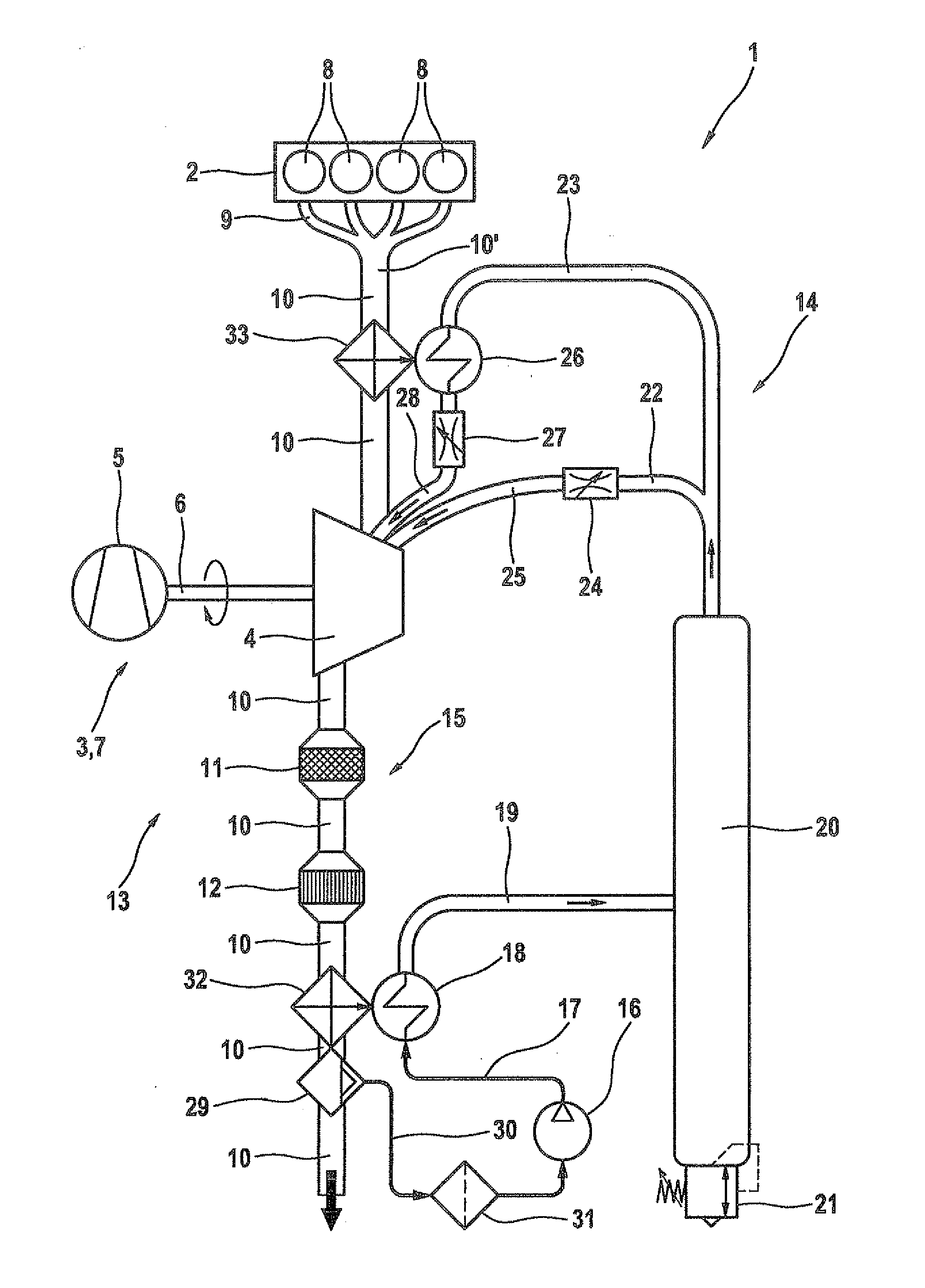
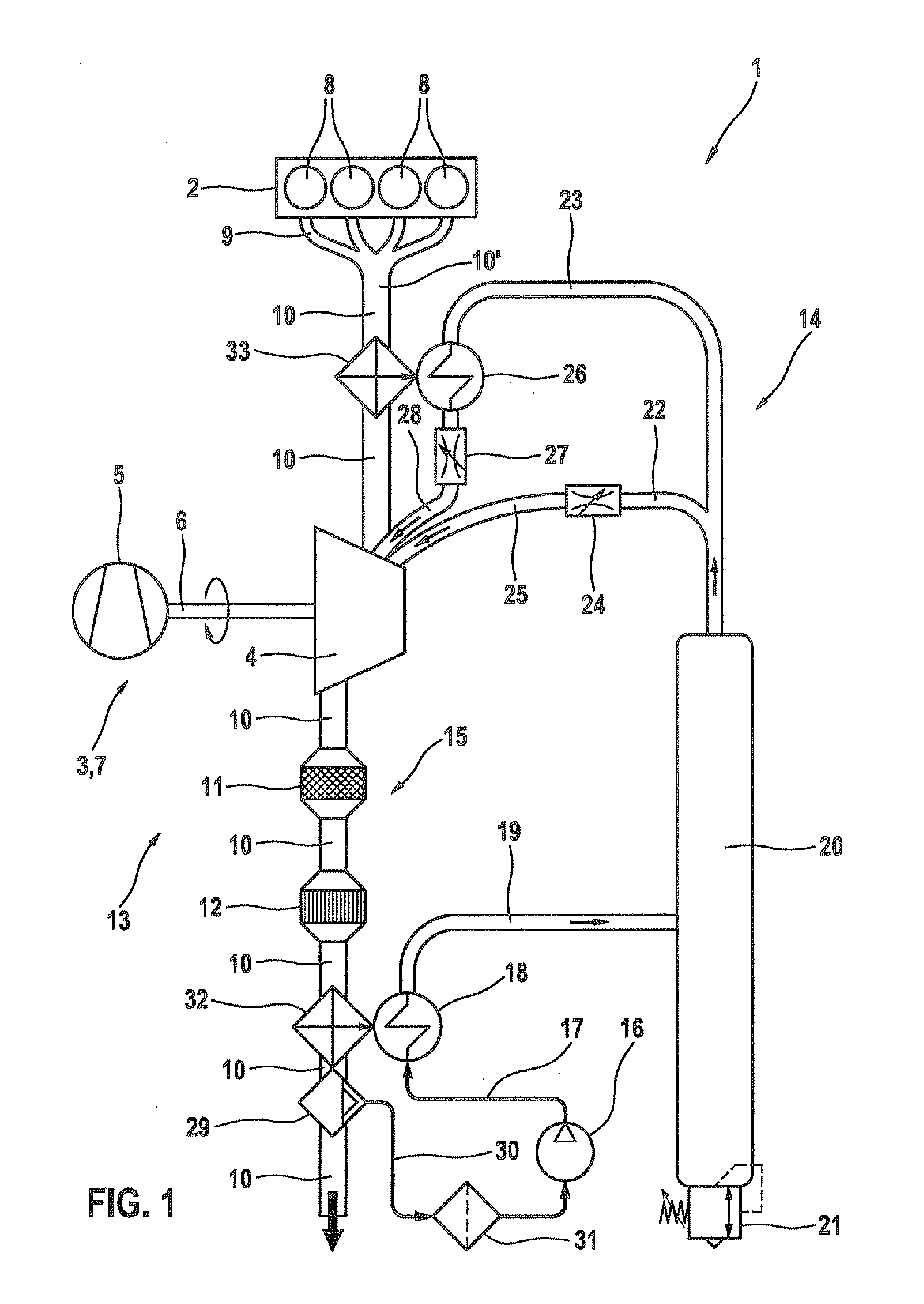
[0031]FIG. 1 shows a first specific embodiment of a driving device 1 having an internal combustion engine 2 and a charging device 3. Charging device 3 has a turbine part 4 that has at least one drive turbine and a compressor part 5, the turbine part and the compressor part being operationally connected via a shaft 6. Charging device 3 is an exhaust gas turbocharger 7 through whose turbine part 4 there flows at least exhaust gas of internal combustion engine 2. Using a turbine wheel provided in turbine part 4, flow energy of the exhaust gas is converted into mechanical energy and is made available to compressor part 5 via shaft 6. Compressor part 5 is in turn used to compress air, in particular drawn from the surrounding environment of driving device 1, thus bringing it to a higher pressure. The compressed air is then supplied to internal combustion engine 2. The resulting exhaust gases coming from cylinders 8 of internal combustion engine 2 are merged by an exhaust manifold 9 and ar...


PUM


Abstract

A driving device having a charging device for increasing the pressure and the mass flow of the combustion air of an internal combustion engine, and having a steam generator for evaporating a fluid using thermal energy drawn from the exhaust gas of the internal combustion engine. The steam generator is connected to a steam accumulator, and the charging device is an exhaust gas turbocharger whose drive turbine can be acted on at least partly both by exhaust gas and also by steam from the steam accumulator, the steam pressure and/or steam mass flow of the steam supplied to the exhaust gas turbocharger being capable of being regulated and/or controlled.

Description

FIELD OF THE INVENTION[0001]The present invention relates to a driving device having a charging device for increasing the pressure and the mass flow of the combustion air of an internal combustion engine, and having a steam generator for evaporating a fluid using thermal energy drawn from the exhaust gas of the internal combustion engine.BACKGROUND INFORMATION[0002]Such driving devices are believed to be understood from the art. For example, DE 10 2006 057 247 A1 discusses a charging device, in particular for charging an internal combustion engine. In an exhaust passage of the internal combustion engine, there is situated at least one heat exchanger of a circuit of the working medium. A conveyor aggregate is connected before the at least one exhaust gas heat exchanger in the circuit of the working medium. Here it is provided that the circuit of the working medium contains at least one turbine part via which at least one compressor part situated in the intake tract of the internal co...

Claims


Application Information

Patent Timeline
Patent Type & Authority Applications(United States)
IPC IPC(8): F02B37/10F02B73/00
CPCF01K3/14F01K23/065F01N5/02F02B37/02Y02T10/16F02B37/10F02B39/08F02B39/085Y02T10/144F02B37/025Y02T10/12
Inventor PROEPPER, THOMAS
Owner ROBERT BOSCH GMBH
Why Eureka
Try Eureka