Cartridge extraction device

a technology of extraction device and cart, which is applied in beverage vessels, household appliances, kitchen equipment, etc., can solve the problems of increasing the risk of hyper-guiding and jamming or improper alignment of the various parts, affecting the extraction conditions, and complicated retaining means of the pod

Active Publication Date: 2012-10-25
SOC DES PROD NESTLE SA
View PDF15 Cites 32 Cited by
  • Summary
  • Abstract
  • Description
  • Claims
  • Application Information

AI Technical Summary

Benefits of technology

[0028]Moreover, by merely releasing pressure in hot parts of the injection arrangement, e.g. an in-line heater of the arrangement, without purging, evaporation-related scale deposition can be inhibited in these hot parts. Indeed such in-line heaters are typically configured to heat a circulating liquid from room temperature to a temperature in the range of 60 to 95° C., in particular 80 to 93° C. During normal use, no evaporation takes place in the heater. However, if the heater is emptied too soon after use, the liquid therein may be evaporated. Therefore, it is preferable to maintain the liquid in the injection arrangement after use instead of purging immediately. Hence, to prevent dripping, the elevated pressure generated by the pump in the liquid is released via the pressure release valve instead of via the cartridge seat and liquid is maintained in the heater to prevent evaporation in the heater and scaling of the heater.
[0055]The liquid injection arrangement may be configured to inject heated liquid into the cartridge seat through a liquid inlet of the seat that is located in the hydraulically actuatable and movable cartridge support. In other words, the same cartridge support of the seat can be associated with the unheated water circulation and with the heated water circulation. Hence, the upstream fluid circulation arrangement leading into the cartridge seat may be maintained in association with one cartridge support only, i.e. it does not have to extend over with both supports. This reduces the length of the connection ducts. Moreover, this can be a significant advantage when the piston chamber is maintained fixed in the extraction device since flexible liquid circulation ducts, which are difficult to assemble in an automatic assembly process, can be minimised or even avoided in favour or rigid ducts that can be assembled automatically.

Problems solved by technology

One problem encountered with the handling of ingredient cartridges is the positioning of the cartridges in an extraction device and the closing of the latter around the cartridge to perform the extraction process in a clean and hygienic manner.
Bad positioning may damage the cartridge, and thus affect the conditions of extraction.
This arrangement involves several problems.
The pod must be moved during the closure of the brewing chamber and this can cause blocking and it also makes the retaining means of the pod more complex.
Moreover, opening and closing the brewing chamber involves simultaneously a linear displacement of the movable rear part within the housing, of the movable front part within the housing and of the outlet duct through the housing which increases the risk of hyper-guiding and jamming or improper alignment of the various parts that linearly move one relative to another.
The fluid system comprises a moving assembly which makes the fluid system more complex to assemble.
Furthermore, an unoccupied volume is left within the machine between the front member and the casing when the outlet duct is in its retracted position.
A problem with using heated water to actuate the closure mechanism lies in the risk of scale deposition from the heated water in the hydraulic mechanism.
One problem with this solution lies in the complication of the parallel water circuits for the hydraulic closure and for the hot injection and the multi-way control valve associated therewith.
Another problem with this system lies in the fact that by having to purge the hydraulic water circuit upon each and every extraction cycle, the circuit must first be replenished before being operative for closing the brewing unit.
However, since the liquid is non-circulating, stagnant in the hydraulic closure system during the extraction process purging is necessary to avoid contamination and hygiene-related issues in this part of the circuit.
Another problem relates to the dripping of liquid form the beverage machine's outlet after a dispensing cycle is over.
Indeed, especially with the preparation of coffee or tea by extracting ground coffee or tea in a brewing chamber that leads to a beverage outlet, drips tend to be formed at the beverage outlet for an extend period of time after the machine's pump has been shut off and the system is not purged to maintain immediate readiness for a further extraction cycle.

Method used


Image

  • Cartridge extraction device
  • Cartridge extraction device
  • Cartridge extraction device

Examples


Embodiment Construction

[0066]The invention is now described with reference to the particular embodiment illustrated in FIGS. 1a to 3.

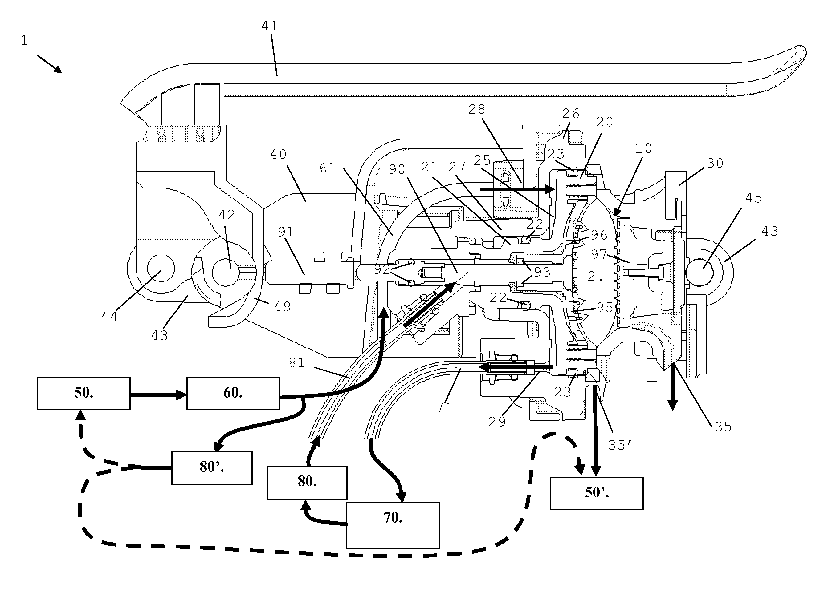
[0067]These Figures show an extraction device 1 of a machine for preparing beverages by circulating heated liquid, such as water, through an ingredient cartridge 2 in the form of a soft pod, e.g. made of a sealed and airtight aluminium envelope containing the beverage ingredient e.g. ground coffee, as for example commercialised by NESPRESSO™.

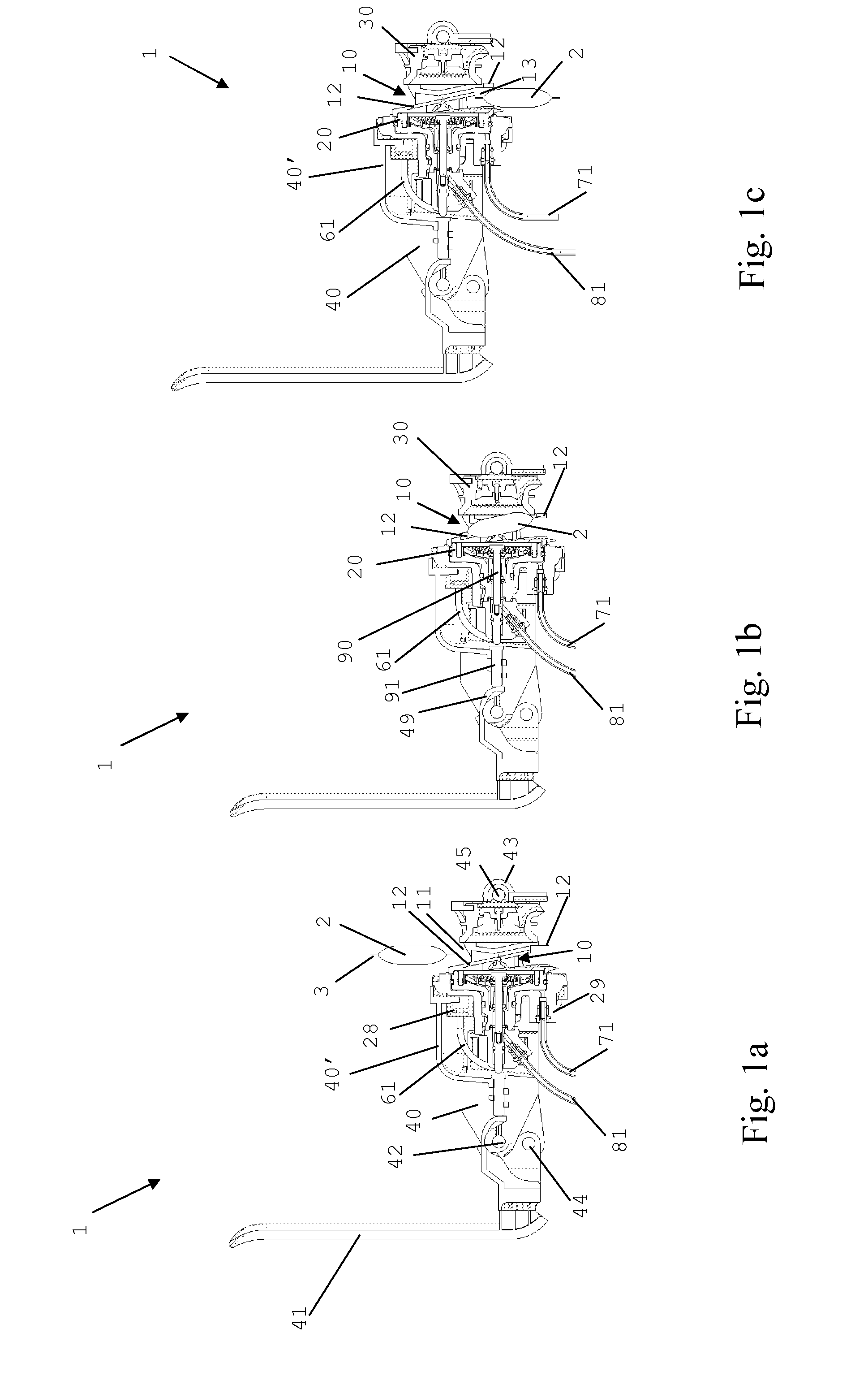
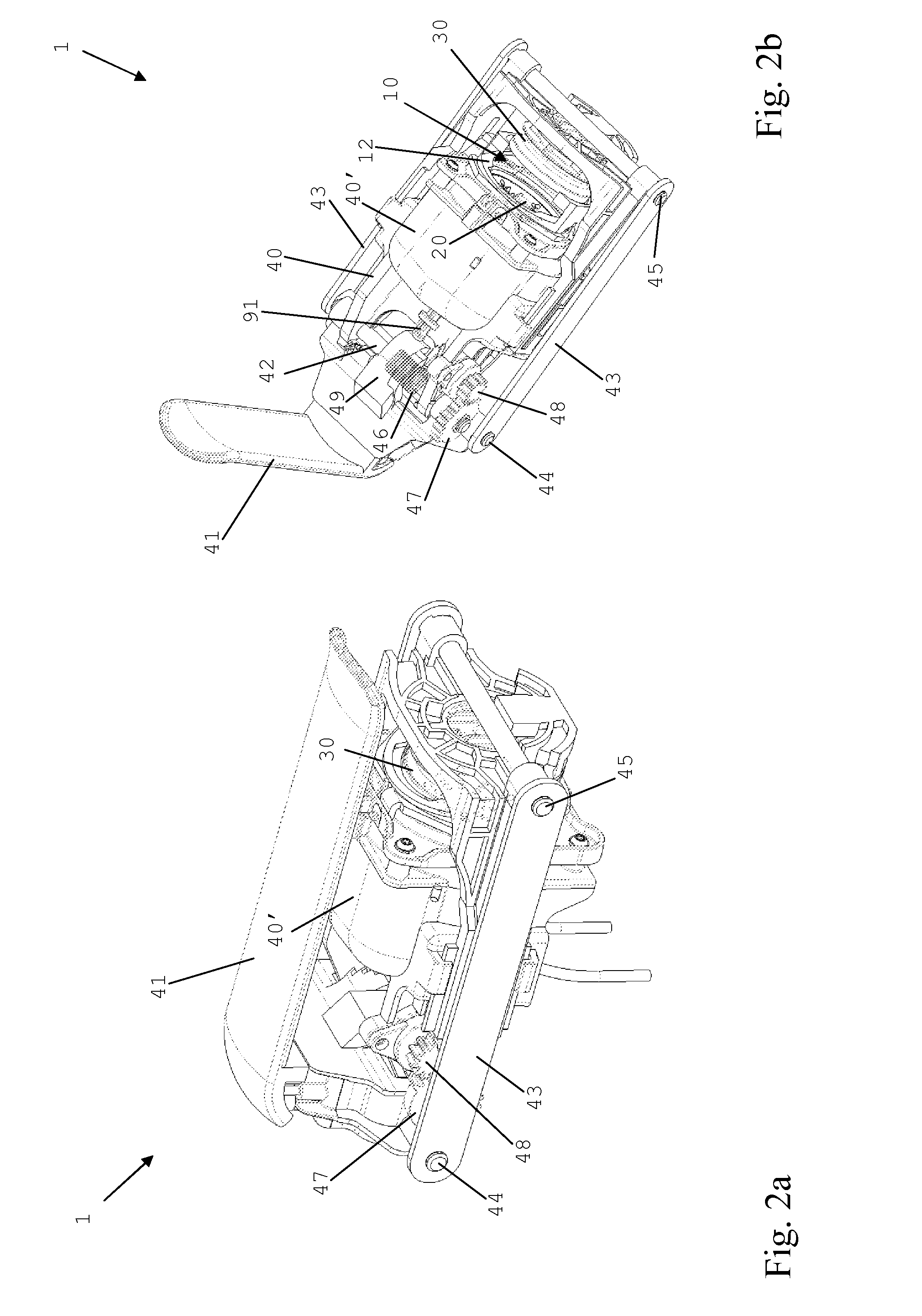
[0068]Extraction device 1 has a cartridge seat 10 comprising a first cartridge support 20 and a second cartridge support 30 facing first cartridge support 20 arranged to receive cartridge 2 in an open spaced apart configuration and to enclose cartridge 2 in a closed urged together extraction configuration. FIGS. 1a, 1b, 1c and 2b illustrate cartridge seat 10 with cartridge supports 20,30 in their open spaced apart configuration. FIGS. 2a and 3 show cartridge seat 10 with cartridge supports 20,30 in their closed urged together extraction ...


PUM


Abstract

A device (1) has: a cartridge seat (10) arranged to receive an ingredient cartridge (2) for extraction; a beverage outlet (35) connected to this cartridge seat for dispensing beverage during extraction; and a liquid injection arrangement (50, 60, 61, 70, 80, 81) comprising a pump (60) for pressurising and circulating liquid from a source (50) via the cartridge seat into the beverage outlet. The liquid injection arrangement further comprises a valve (80′) between the pump and the cartridge seat. The liquid injection arrangement is configured to release via the valve (80′) pressure from this pressurised liquid in the injection arrangement and maintain liquid in the injection arrangement from the pump (60) to the cartridge seat (10) after the pump is stopped, so as to inhibit dripping from the beverage outlet (35).

Description

FIELD OF THE INVENTION[0001]The present invention relates to a cartridge extraction device with a cartridge seat formed by two facing cartridge supports that is arrangement for managing the formation of drips at the device's outlet after the end of an extraction cycle. The extraction device may in particular be used in beverage preparation machines.[0002]For the purpose of the present description, a “beverage” is meant to include any liquid food, such as tea, coffee, hot or cold chocolate, milk, soup, baby food, etc. . . . . Cartridges designate any enclosure for containing a pre-portioned ingredient whether rigid, such as capsules, or soft or flexible, such as pods, and made of any material, recyclable or non recyclable, biodegradable or non-biodegradable, such as aluminium or plastic, in particular aluminium pods or aluminium capsules.BACKGROUND ART[0003]One problem encountered with the handling of ingredient cartridges is the positioning of the cartridges in an extraction device ...

Claims


Application Information

Patent Timeline
Patent Type & Authority Applications(United States)
IPC IPC(8): A47J31/44
CPCA47J31/3633A47J31/407A23L2/52A47J31/46A47J31/469
Inventor BAUDET, PATRICKLARZUL, DAVIDJACCARD, ALAINRITHENER, BLAISE
Owner SOC DES PROD NESTLE SA
Why Eureka
Try Eureka