Solar-energy collector/concentrator with cassegrain-type optics

a technology of solar energy collector and concentrater, which is applied in the direction of solar-ray concentration, photovoltaics, heat collector mounting/support, etc., can solve the problems of affecting the effect of the cooling device, affecting the cooling effect, and the base cannot guarantee the accuracy, so as to prevent the premature aging reduce the irregularity of the reflective surface, and improve the resistance and stability of the plastic material

Inactive Publication Date: 2012-10-25
SOLTEC ENERGIAS RENOVABLES
View PDF6 Cites 12 Cited by
  • Summary
  • Abstract
  • Description
  • Claims
  • Application Information

AI Technical Summary

Benefits of technology

[0011]By virtue of the peripheral leg ends, the base body is capable of supporting the primary reflector in a very stable manner on said supporting surface and, at the same time, positioning the primary reflector relative to the transparent panel, with the secondary reflector being supported thereon. The base body maintains the primary reflector free from mechanical loads, thus ensuring the integrity of the geometry thereof and preventing its premature aging. In addition, the base body can be linked to a base panel providing said supporting surface.
[0012]Preferably, the base body further comprises second connection members connecting the mutually adjacent peripheral legs, both the first and second connection members having respective top edges configured to be in contact with an underside of the primary reflector, whereby the primary reflector is very well seated on the base body. In one preferred embodiment, the primary reflector comprises a structural substrate obtained by injection moulding of a plastic material, which is metallised, for example with silver o aluminium, on the concave surface thereof. Manufacturing the structural substrate of the primary reflector and the base body as two separate pieces has the advantage of minimising the irregularities on the reflective surface, since the moulded configurations on the side of structural substrate opposite the reflective surface might cause undesirable deformations therein, and, in addition, it allows for manufacturing both pieces with different plastic materials, for example a more resistant and stable plastic material for the structural substrate and a more common material for the base body.
[0013]The fact that the structural substrate of the primary reflector and the base body should be separate pieces obtained by injection moulding of a plastic material further allows for the formation of the structural substrate and the base body with respective mutual snap lock first coupling configurations in said region around the central opening of the primary reflector and on the central support of the base body and respective mutual snap lock second coupling configurations in said peripheral regions of the primary reflector and in the peripheral legs of the base body. Thus, the assembly of the primary reflector to the base body can be carried out in an easy, fast manner, without the use of tools, and with complete reliability regarding mutual positioning. Preferably, the secondary reflector also comprises a structural substrate obtained by injection moulding of a plastic material with metallisation of the convex surface thereof, and it is attached to the transparent panel, for example by means of an adhesive.

Problems solved by technology

On the other hand, the radiation concentration causes a considerable temperature rise in the collector and regions adjacent thereto, which forces the provision of cooling means.
A drawback of the collector / concentrator of the cited International Patent Application WO 2006 / 030433 is that the base does not guarantee an accurate positioning of the primary reflector, since it only covers a small central region thereof, which may be the cause of orientation errors and loss of effectiveness, specially when the collector / concentrator units are clustered together in one prefabricated module.
Another drawback is that the cooling system made up by a chamber in communication with a cooling fluid circuit is complex and costly to manufacture and it requires regular maintenance.
The fact of having the primary reflector directly in contact with the transparent panel has the drawback of introducing mechanical loadings potentially harmful to the system.
The weight of the primary reflector itself or its interaction with other parts for which it acts as a support might produce undesirable deformations in the transparent panel or shorten its lifetime, diminishing the concentrator performance.

Method used


Image

  • Solar-energy collector/concentrator with cassegrain-type optics
  • Solar-energy collector/concentrator with cassegrain-type optics
  • Solar-energy collector/concentrator with cassegrain-type optics

Examples


Embodiment Construction

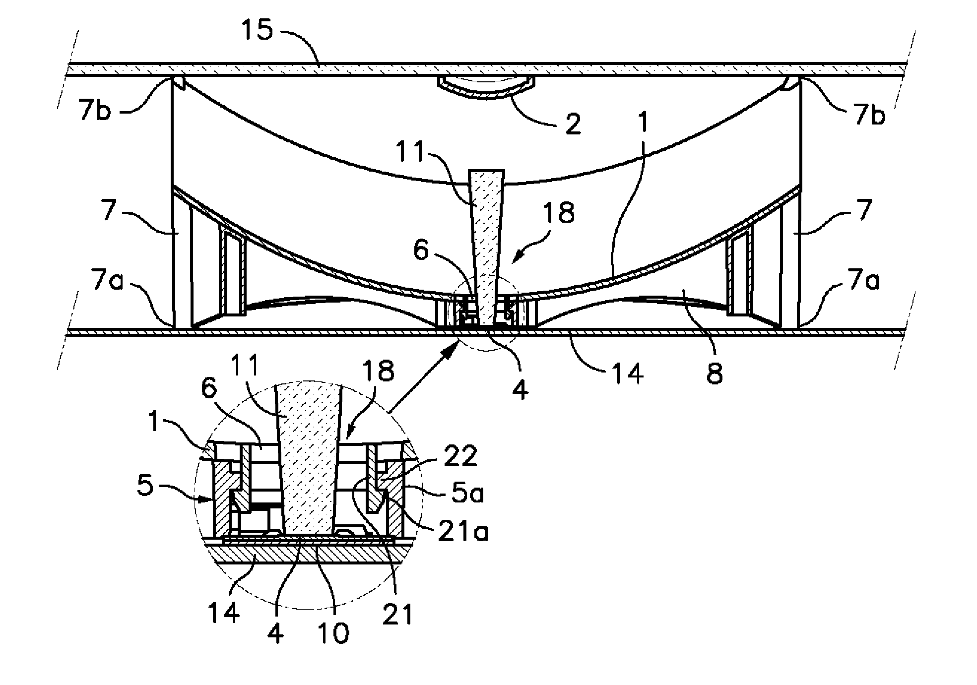
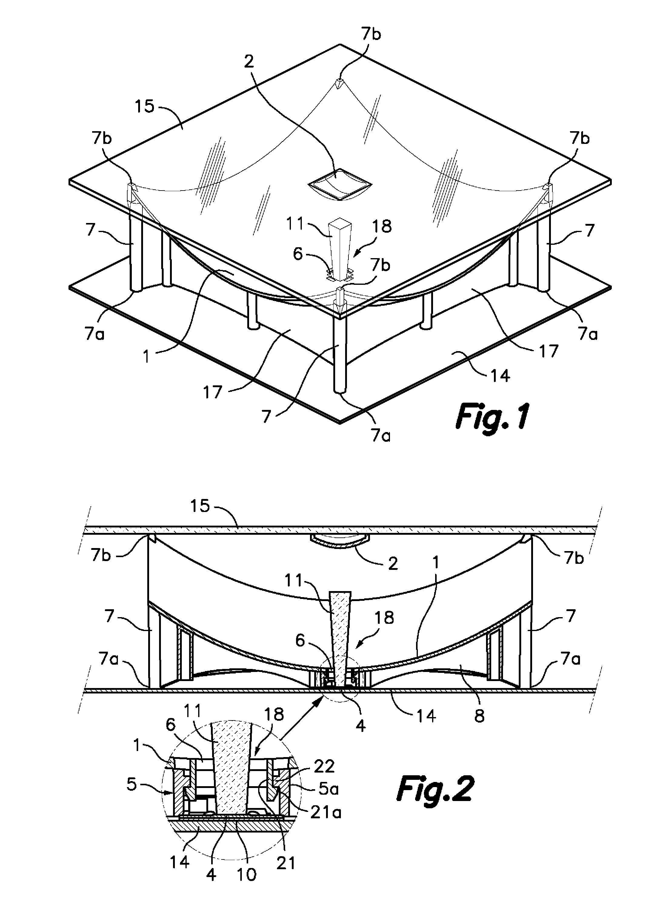
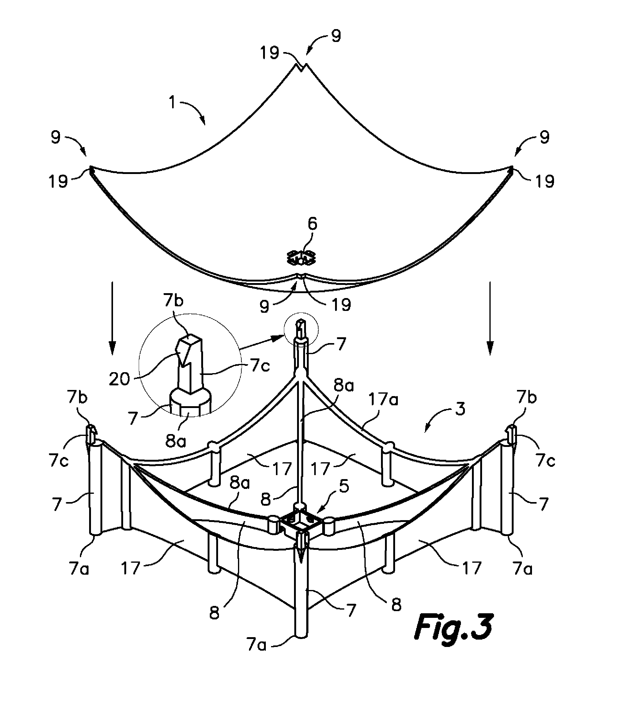
[0033]Referring first to FIGS. 1 to 6, there is shown a solar energy collector / concentrator unit with Cassegrain-type optics according to one embodiment of the present invention that comprises a primary concave reflector 1 supported on a base body 3 that leans on a substantially flat supporting surface, provided, for example, by a base panel 14, a secondary convex reflector 2 supported by a substantially flat transparent panel 15 above said primary reflector 1, and a receiver unit 18 arranged below said primary reflector and opposite said secondary reflector 2 through a central opening 6 formed in the primary reflector 1.

[0034]As shown in FIGS. 2, 5A and 5B, said receiver unit 18 comprises a photovoltaic cell 4 mounted, together with electric and electronic components, on a receiver plate 10. The receiver unit 18 also comprises a radiation guide 11 in the shape of a solid frustopyramidal block made of a transparent material, such as, for example, BK7 glass, and it has a base surface...


PUM


Abstract

The collector / concentrator includes a primary concave reflector (1) supported on a base body (3) obtained by injection moulding, which defines a central support (5) supporting a region around a central opening (6) of the primary reflector (1), a plurality of peripheral legs (7) supporting respective peripheral regions of the primary reflector (1) and first integral connection members (8) connecting said peripheral legs (7) with the central support (5). The peripheral legs (7) have bottom ends (7a) leaning on a substantially flat supporting surface and top ends (7b) located above the peripheral regions of the primary reflector (1) that are in contact with a substantially flat transparent panel (15) supporting a secondary convex reflector (2) that concentrates the solar radiation reflected by the primary reflector (1) towards a receiver unit (18) through the central opening (6).

Description

FIELD OF THE ART[0001]The present invention relates to a solar energy collector / concentrator with Cassegrain-type optics wherein the primary and secondary reflectors comprise a plastic substrate obtained by injection moulding and afterwards metallised, and the secondary reflector is supported by a base likewise obtained by injection moulding of a plastic material.BACKGROUND OF THE INVENTION[0002]Solar energy collector / concentrators provided with a Cassegrain-type optical system for concentrating the solar radiation captured through a collector of relatively large dimensions in a receiver of relatively small dimensions are well known. In this type of collector / concentrator, the collector is a primary concave reflector that is arranged to reflect and concentrate the captured solar radiation towards a secondary smaller convex reflector, which is located above the primary reflector and arranged in turn to reflect and concentrate the solar radiation from the primary reflector towards the...

Claims


Application Information

Patent Timeline
Patent Type & Authority Applications(United States)
IPC IPC(8): H01L31/052G02B5/10F24S23/70F24S23/79
CPCF24J2/12F24J2/18F24J2/5256Y02E10/42H01L31/0547Y02E10/52F24J2/067F24J2/5237Y02E10/47F24S23/12F24S23/71F24S23/79F24S25/11F24S25/634Y02E10/40
Inventor GRANT, THOMASTERUEL HERNANDEZ, JOSE ALFONSOMORALES TORRES, RA L
Owner SOLTEC ENERGIAS RENOVABLES
Why Eureka
Try Eureka