

Rubber composition for tire, and pneumatic tire
- Summary
- Abstract
- Description
- Claims
- Application Information
AI Technical Summary
Benefits of technology
Problems solved by technology
Method used
Image

Examples
examples
[0079]The invention is illustrated more concretely below by way of examples, although the examples are not intended to limit the invention.
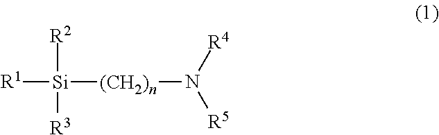
[0080]The various chemicals used in the examples of the invention and the comparative examples are described below.[0081]NR: TSR20[0082]Unmodified SBR: Nipol 1502 (E-SBR; bound styrene content: 23.5% by mass; unmodified), from Zeon Corporation[0083]High-cis BR: VCR617 (SPB-containing BR; SPB content: 17% by mass; SPB melting point: 200° C.; boiling n-hexane insolubles content: 15% to 18% by mass), from Ube Industries, Ltd.[0084]Modified SBR: HPR340 (modified S-SBR; bound styrene content: 10% by mass; Tg: −64° C.; terminally modified with an alkoxysilane by coupling; modified with a compound of formula (1) (R1 to R3=methoxy; R4 and R5=hydrogen atoms; n=3)), from JSR Corporation[0085]Modified BR: BR1250H (tin-modified BR polymerized using a lithium initiator; vinyl content: 10% to 13% by mass; Mw / Mn: 1.5; tin atom content: 250 ppm), from Zeon Corpo...
PUM
| Property | Measurement | Unit |
|---|---|---|
| Temperature | aaaaa | aaaaa |
| Temperature | aaaaa | aaaaa |
| Percent by mass | aaaaa | aaaaa |
Abstract
Description
Claims
Application Information