Power converting circuit and feedback control circuit
a technology of power conversion circuit and feedback control circuit, which is applied in the direction of electric variable regulation, process and machine control, instruments, etc., can solve the problems of severe overshooting or undershooting events, output voltage vout, etc., and achieve the effect of improving operational safety
- Summary
- Abstract
- Description
- Claims
- Application Information
AI Technical Summary
Benefits of technology
Problems solved by technology
Method used
Image

Examples
first embodiment
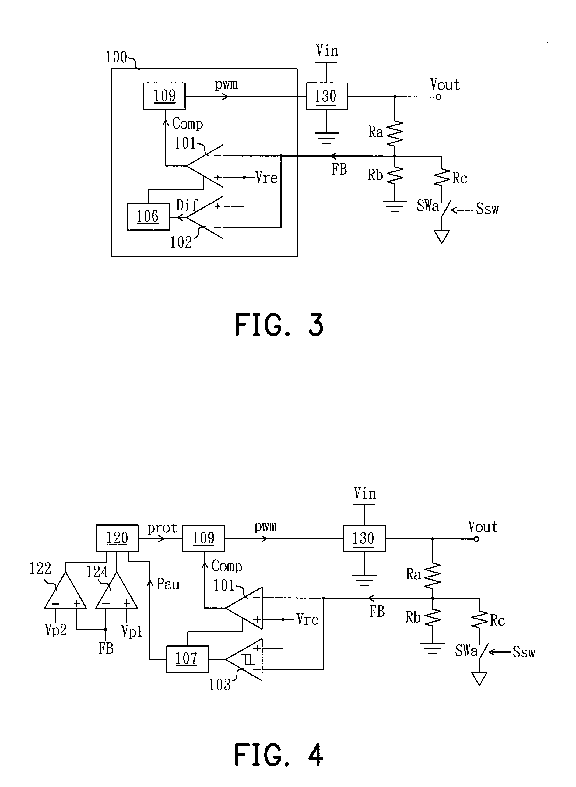
[0023]FIG. 3 is a circuit diagram of a power converting circuit in accordance with the present invention. The power converting circuit includes a feedback control circuit 100 and a converting unit 130. The converting unit 130 is coupled to an input power source Vin for converting the input power source Vin into an output voltage Vout. The converting unit 130 may be a DC-DC converting circuit, such as a DC-DC boost converter, a DC-DC buck converter, a DC-DC buck-boost converter, a DC-DC flyback converter, a DC-DC forward converter, a DC-DC half-bridge converter, a DC-DC full-bridge converter, and etc. The power converting circuit also has a voltage divider which includes resistors Ra and Rb serially connected between the output end of the converting unit 130 and a ground for generating a feedback signal FB according to the output voltage Vout. The voltage divider also has a resistor Rc and a switch SWa. One end of the resistor Rc is coupled to a junction between the resistors Ra and ...
second embodiment
[0026]FIG. 4 is a circuit diagram of a power converting circuit in accordance with the present invention. As shown, the power converting circuit includes a feedback control circuit and a converting unit 130. The feedback control circuit includes am amplifier 101, an amplifier modulating unit, an output protection unit, and a duty-cycle control unit 109. The amplifier modulating unit includes an error hysteresis determining unit 103 and a modulating unit 107. The output protection unit includes an over-voltage determining unit 122, an under-voltage determining unit 124, and a protection determining unit 120. The error hysteresis determining unit 103 receives a reference voltage signal Vre and a feedback signal FB and alters its output logic as the level of the feedback signal FB is lower than a first predetermined voltage level or higher than a second predetermined voltage level. For example, as the level of the feedback signal FB is over or under a predetermined modulating ratio, su...
third embodiment
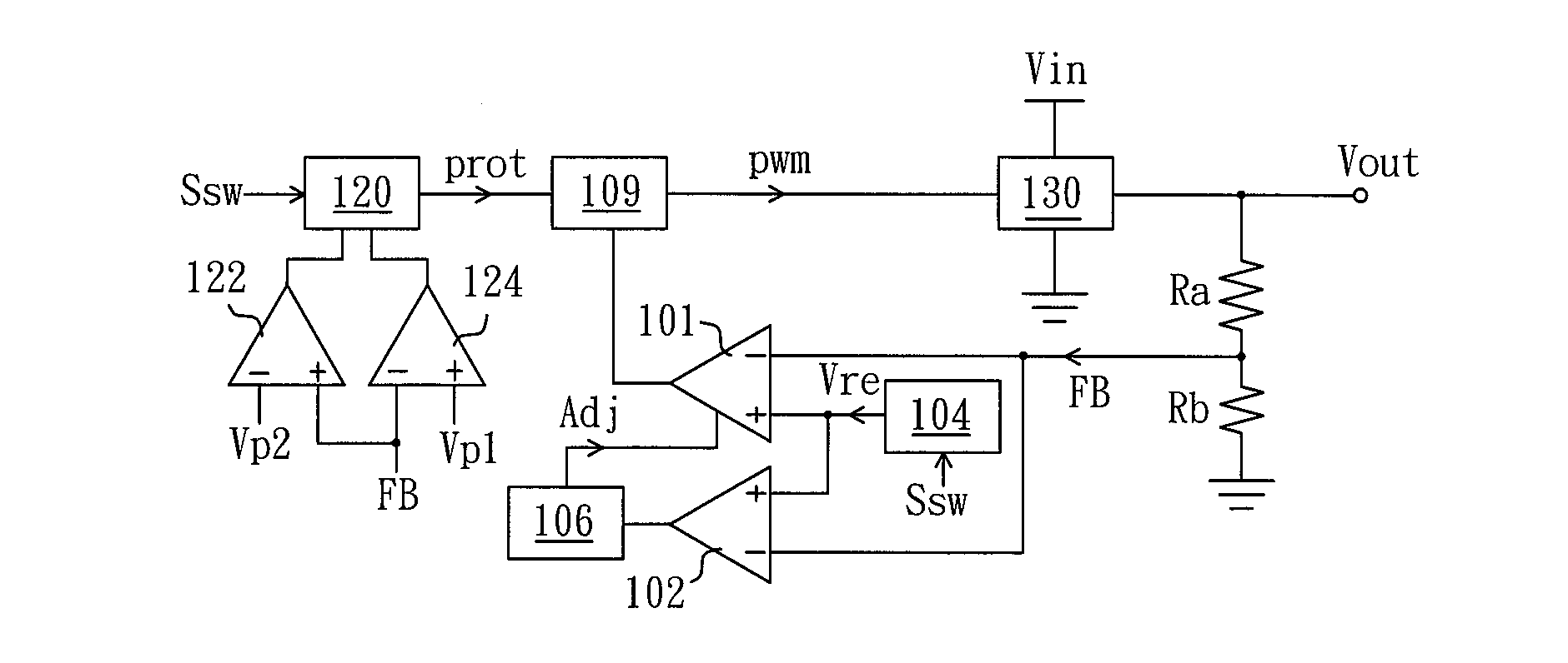
[0028]FIG. 5 is a circuit diagram of a power converting circuit in accordance with the present invention. In contrast with the embodiments in FIGS. 3 and 4, the present invention achieves the object of adjusting the level of the output voltage Vout through modulating the level of the reference voltage signal according to the level adjusting signal Ssw. The power converting circuit includes a feedback control circuit and a converting unit 130. The feedback control circuit includes an amplifier 101, an amplifier modulating unit, an output protection unit, and a duty-cycle control unit 109. The amplifier modulating unit includes an error determining unit 102 and a modulating unit 106. The output protection unit includes an over-voltage determining unit 122, an under-voltage determining unit 124, and a protection determining unit 120. The circuit operation of the amplifier modulating unit, the under-voltage determining unit 124, and the protection determining unit 120 may be referred to...
PUM
 Abstract
Description
Claims
Application Information
 - R&D
- Intellectual Property
- Life Sciences
- Materials
- Tech Scout
- Unparalleled Data Quality
- Higher Quality Content
- 60% Fewer Hallucinations
Browse by: Latest US Patents, China's latest patents, Technical Efficacy Thesaurus, Application Domain, Technology Topic, Popular Technical Reports.
© 2025 PatSnap. All rights reserved.Legal|Privacy policy|Modern Slavery Act Transparency Statement|Sitemap|About US| Contact US: help@patsnap.com