Current sensor operating in accordance with the principle of compensation

a current sensor and compensation principle technology, applied in the direction of magnetic measurements, instruments, measurement devices, etc., can solve the problems of reduced reliability or increased design effort in cooling means and components, sensor size and cost, and total loss and supply power demand of sensors

Active Publication Date: 2012-10-25
ABB (SCHWEIZ) AG
View PDF2 Cites 15 Cited by
  • Summary
  • Abstract
  • Description
  • Claims
  • Application Information

AI Technical Summary

Benefits of technology

[0009]An exemplary current sensor is disclosed, comprising: a primary coil, through which current to be measured flows, creating a first magnetic field; a secondary coil, through which a compensation current flows, generating a magnetic field compensating the first magnetic field of the primary coil; a gapped magnetic core, magnetically coupled to the two primary and secondary coils and concentrating the resulting magnetic field in its air gap; a terminating resistor connected in series with the secondary coil; sensor means located in the air gap and exposed to the resulting magnetic field of ...

Problems solved by technology

This residual induction corresponds to a current error of the whole sensor and needs to be kept small.
These semiconductor losses will contribute to the total losses and the supply power demand of the sensor.
Moreover, they may give rise to local heating in the sensor, leading ...

Method used


Image

  • Current sensor operating in accordance with the principle of compensation
  • Current sensor operating in accordance with the principle of compensation
  • Current sensor operating in accordance with the principle of compensation

Examples


Embodiment Construction

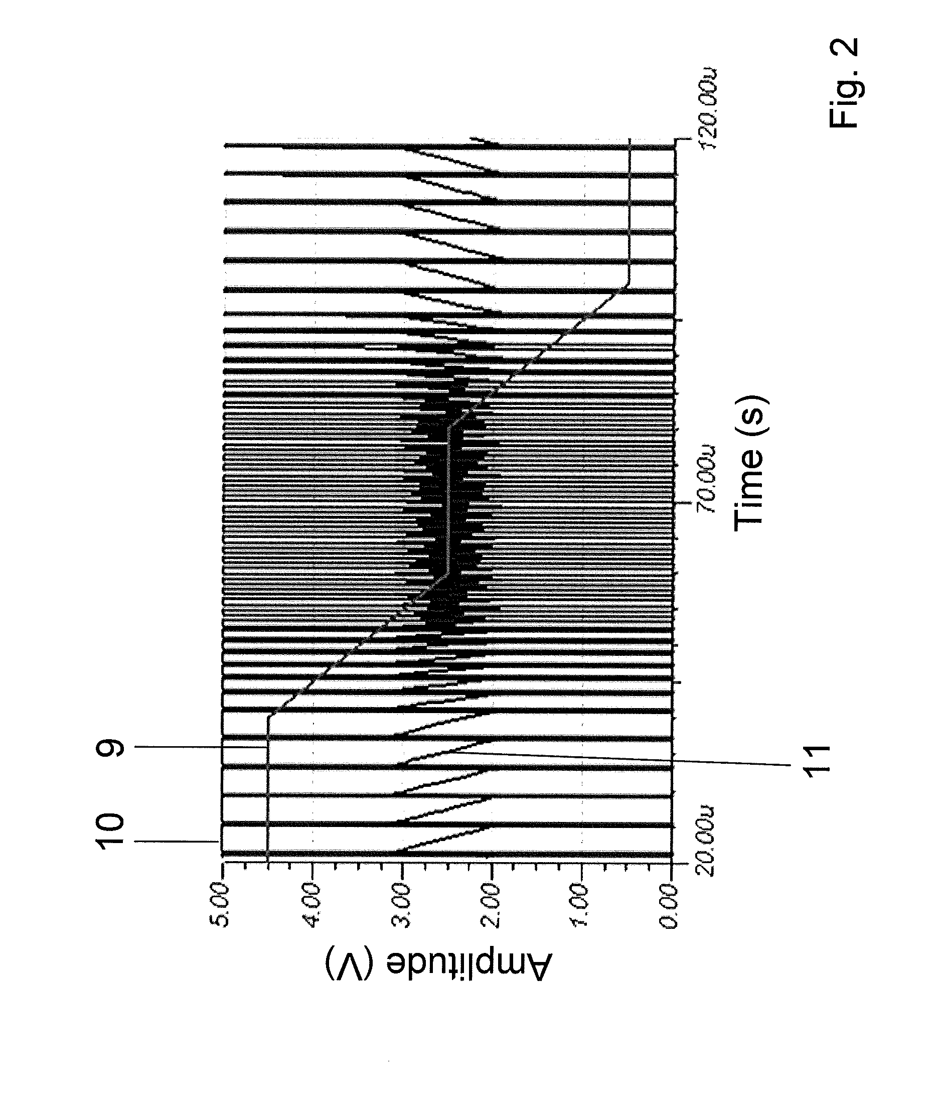
[0020]Exemplary embodiments of the present disclosure reduce semiconductor losses at high currents, and relative ripple value at small currents.

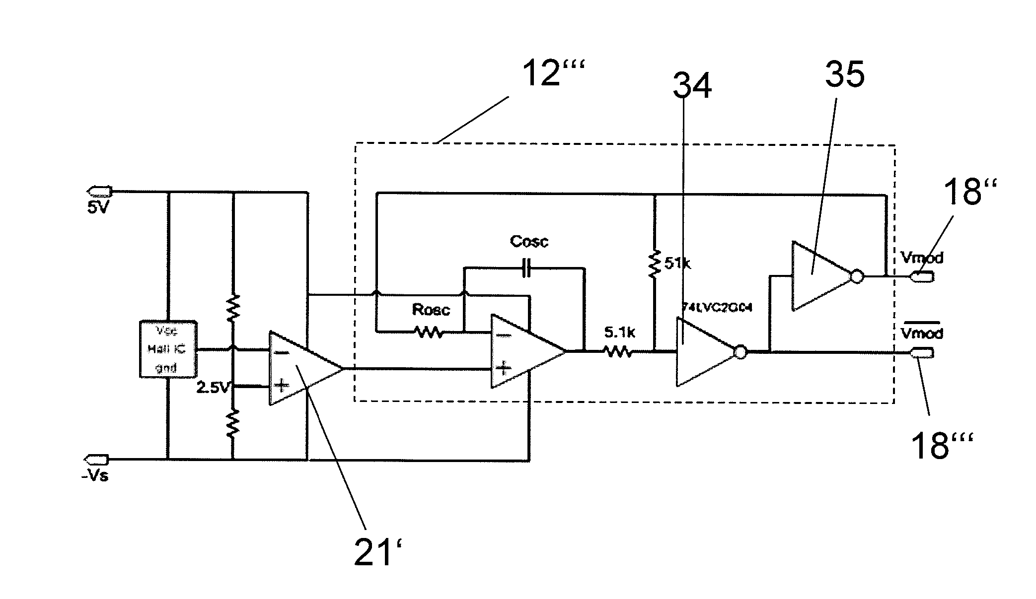
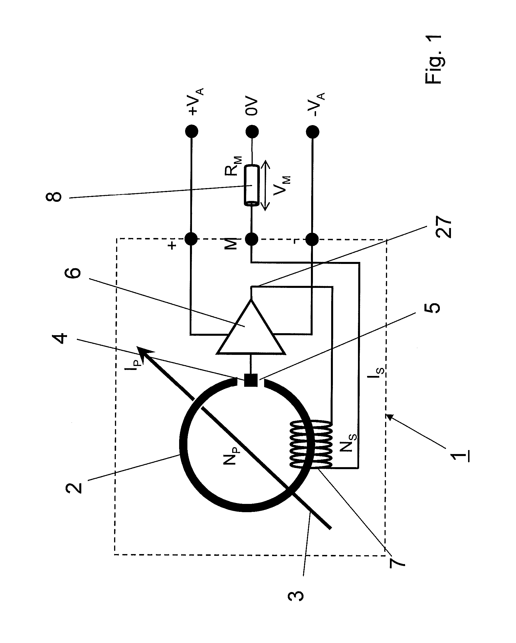
[0021]According to an exemplary embodiment disclosed herein a current sensor operating in accordance with the principle of compensation, has a booster circuit which includes a switched mode amplifier with a pulse width and density modulator that generates a pulse width and density modulated voltage signal, which drives the compensation current through the secondary winding after an appropriate filtering. The switching frequency of such modulator is a function of the compensation current in the sense that the switching frequency is high at small currents and low at high currents.

[0022]According to another exemplary embodiment, the switching frequency with pulse width and density modulation is highest at small output current and lowest at large currents. The switching losses are therefore lowest at large current when the conduction losses are ...


PUM


Abstract

An exemplary current sensor operating in accordance with the principle of compensation includes a primary winding creating a magnetic field based on a current to be measured, a secondary winding generating a magnetic field compensating the primary winding based on a compensation current. The current sensor also includes a magnetic core, a terminating resistor connected in series to the secondary winding, and sensor means. A booster circuit is connected downstream of the sensor means and feeds the compensation current to the secondary winding via the terminating resistor. The booster circuit includes a switched mode amplifier with a pulse width and density modulator that operates based on pulse width and density modulation, turning the compensation current into a pulse width and density modulated current. The switched mode amplifier having a switching frequency that is high at when the compensation current is small and low when the compensation current is high.

Description

RELATED APPLICATION(S)[0001]This application claims priority under 35 U.S.C. §119 to European Patent Application No. 11003400.6 filed in Europe on Apr. 21, 2011, the entire content of which is hereby incorporated by reference in its entirety.FIELD[0002]The disclosure relates to a current sensor operating in accordance with the principle of compensation, the sensor including a primary coil winding through which the current to be measured flows and creates a magnetic field.BACKGROUND INFORMATION[0003]Known current sensors operating in accordance with the principle of compensation are often also called closed loop current sensors. Closed loop current sensors are based on a magnetic circuit, called core, of a highly permeable material which encloses a primary winding with the current that is to be measured. A flux sensor element located in the magnetic circuit, e.g. in an air gap, will detect any magnetic flux induced in this circuit and will generate a proportional signal. This signal ...

Claims


Application Information

Patent Timeline
IPC IPC(8): G01R35/00
CPCG01R15/202G01R15/185G01R33/0005G01R33/07
Inventor HOZOI, ADRIANDISSELNKOTTER, ROLF
Owner ABB (SCHWEIZ) AG
Why Eureka
Try Eureka