X-ray source with high-temperature electron emitter

a high-temperature electron emitter and x-ray source technology, applied in the field of x-ray sources, can solve problems such as limiting the resolution of x-ray point projection microscopes

Inactive Publication Date: 2012-10-25
ADLER DAVID L +1
View PDF14 Cites 61 Cited by
  • Summary
  • Abstract
  • Description
  • Claims
  • Application Information

AI Technical Summary

Problems solved by technology

These x-ray-source sizes may limit the resolution of an x-ray point projection microscope.

Method used


Image

  • X-ray source with high-temperature electron emitter
  • X-ray source with high-temperature electron emitter
  • X-ray source with high-temperature electron emitter

Examples


Embodiment Construction

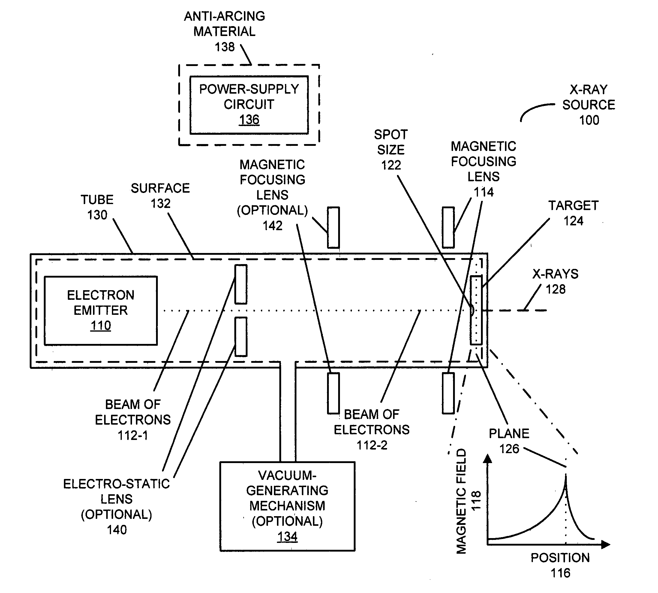
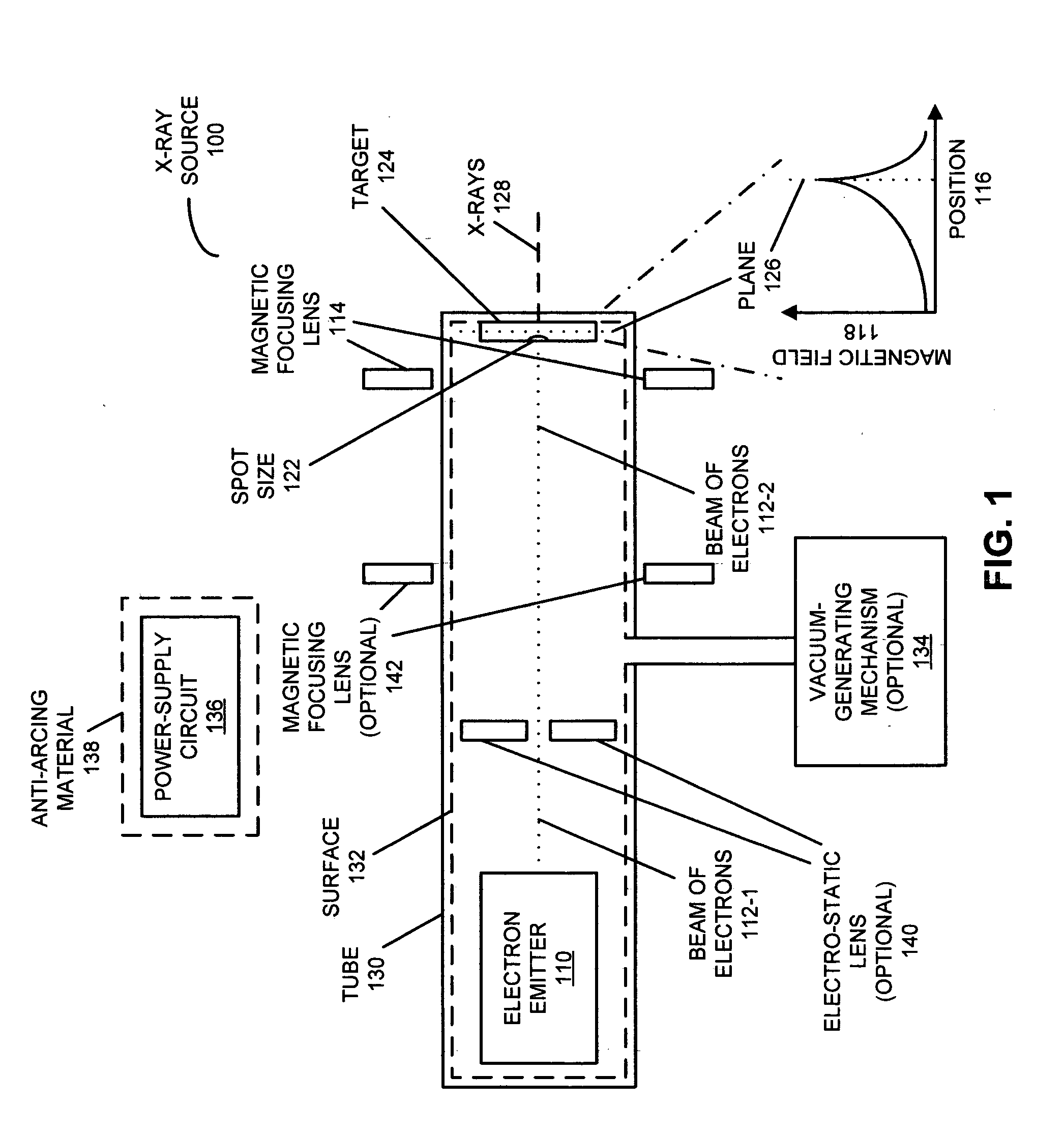
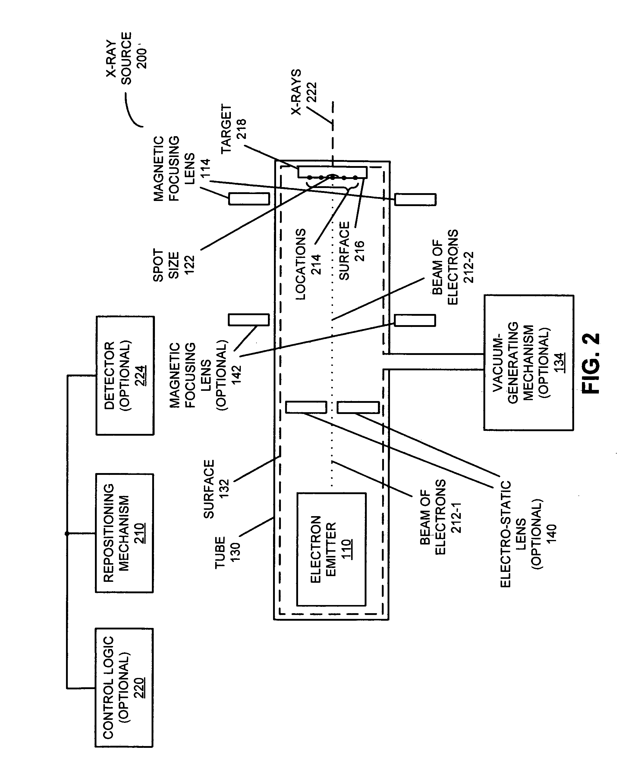
[0032]Embodiments of an x-ray source and associated methods are described. During operation of the x-ray source, an electron source emits a beam of electrons. Moreover, a repositioning mechanism selectively repositions the beam of electrons on a surface of a target based on a feedback parameter, where a location of the beam of electrons on the surface of the target defines a spot size of x-rays output by the x-ray source. In response to receiving the beam of electrons, the target provides a transmission source of the x-rays. Furthermore, a beam-parameter detector provides the feedback parameter based on a physical characteristic associated with the beam of electrons and / or the x-rays output by the x-ray source. This physical characteristic may include: at least a portion of an infrared spectrum or a visible spectrum emitted by the target when it receives the beam of electrons; secondary electrons emitted by the target based on a cross-sectional shape of the beam of electrons; an int...


PUM

PropertyMeasurementUnit
voltageaaaaaaaaaa
voltageaaaaaaaaaa
diameteraaaaaaaaaa

Abstract

An x-ray source is described. This x-ray source includes an electron source with a refractory binary compound having a melting temperature greater than that of tungsten. For example, the refractory binary compound may include: hafnium carbide, zirconium carbide, tantalum carbide, lanthanum hexaboride and / or compounds that include two or more of these elements.

Description

CROSS REFERENCE TO RELATED APPLICATIONS[0001]This application claims priority under 35 U.S.C. 120 to U.S. Non-provisional patent application Ser. No. 13 / 066,679, entitled “X-ray Source with Selective Repositioning of Electron Beam,” by David L. Adler et al., filed on Apr. 21, 2011, the contents of which are herein incorporated by reference.[0002]This application is also related to U.S. Non-provisional patent application Ser. No. ______, entitled “X-ray Source with an Immersion Lens,” by David L. Adler et al., filed on Nov. ______, 2011, and to U.S. Non-provisional patent application Ser. No. ______, entitled “X-ray Source with Increased Operating Life,” by David L. Adler et al., filed on ______, 2011.FIELD OF THE INVENTION[0003]The present disclosure relates generally to an x-ray source and associated methods. More specifically, the present disclosure relates to an x-ray source that includes an electron source with a refractory binary compound having a melting temperature greater th...

Claims


Application Information

Patent Timeline
Patent Type & Authority Applications(United States)
IPC IPC(8): H01J35/14
CPCH01J35/08H01J35/14H05G1/52H01J2235/087H01J2235/186H01J35/116H01J35/186H01J35/147H01J35/153
Inventor ADLER, DAVID L.MACKIE, WILLIAM ANSEL
Owner ADLER DAVID L
Why Eureka
Try Eureka