
Aortic bioprosthesis and systems for delivery thereof

a bioprosthesis and aortic valve technology, applied in the field of systems, methods and devices for cardiac valve replacement, can solve the problems of valve regurgitation, poor valve functioning, and inability of surgeons to ensure proper positioning and stability of the replacemen

Active Publication Date: 2012-10-25
BOSTON SCI LTD
View PDF49 Cites 223 Cited by
  • Summary
  • Abstract
  • Description
  • Claims
  • Application Information

AI Technical Summary

Benefits of technology

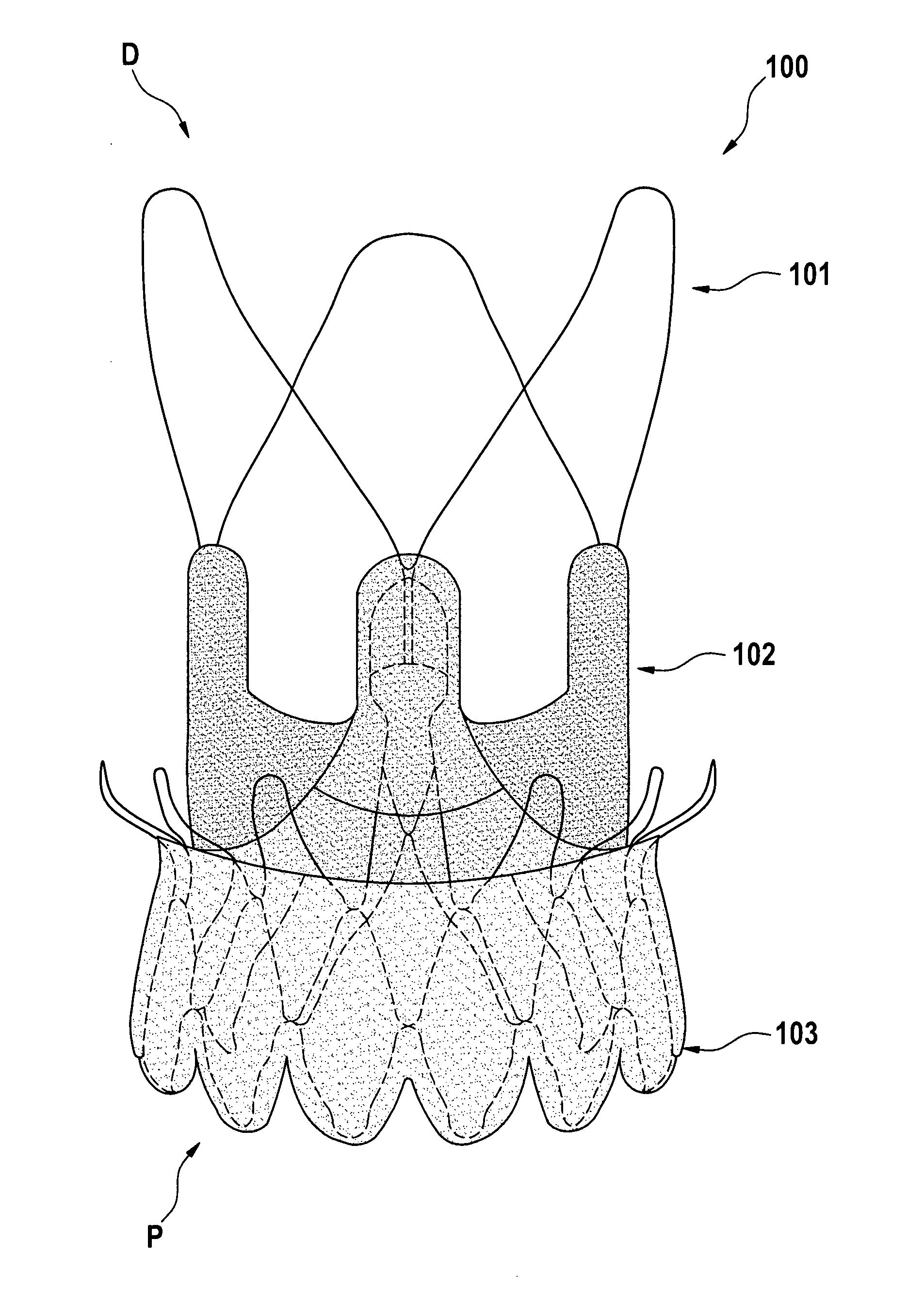
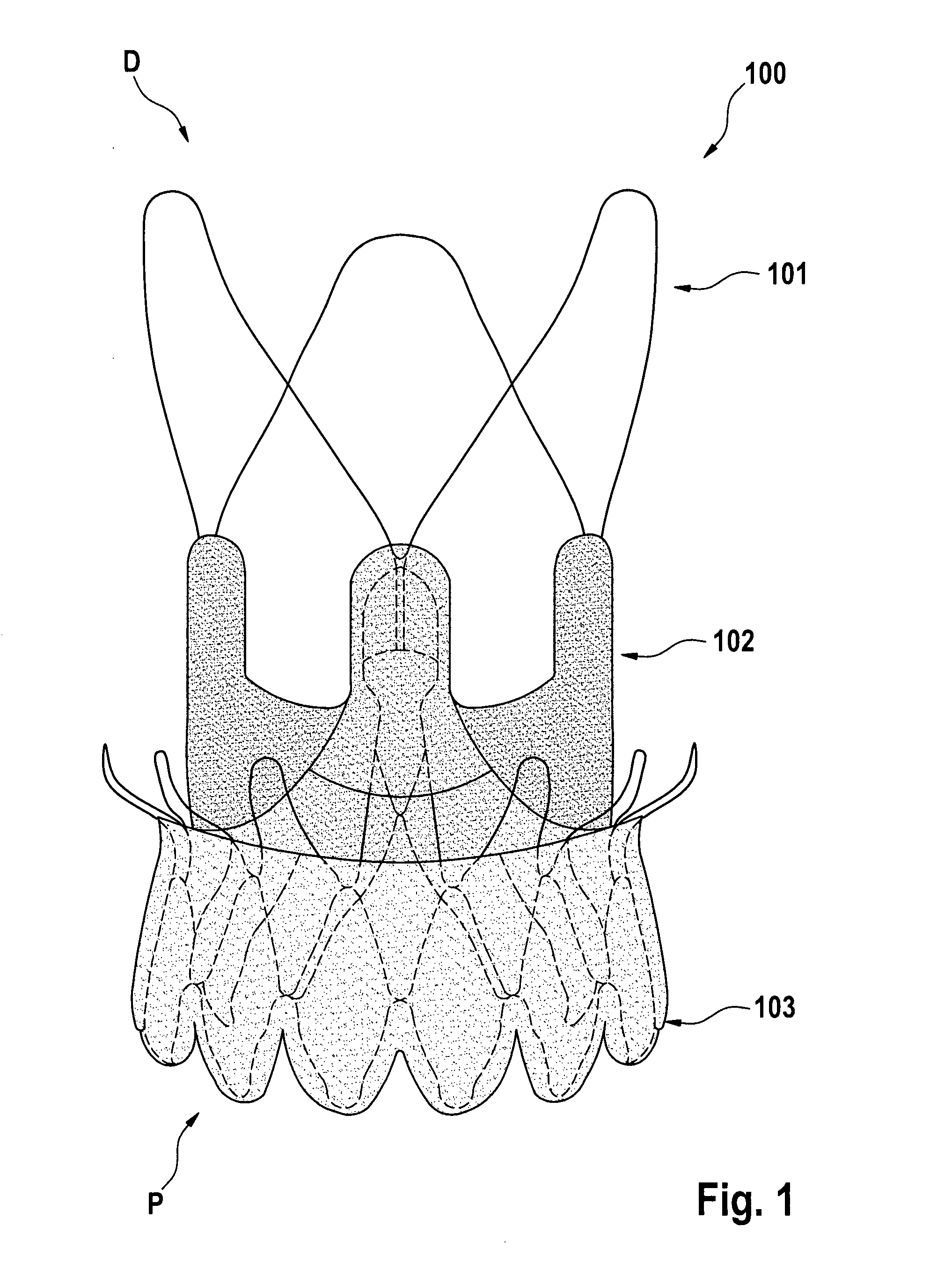
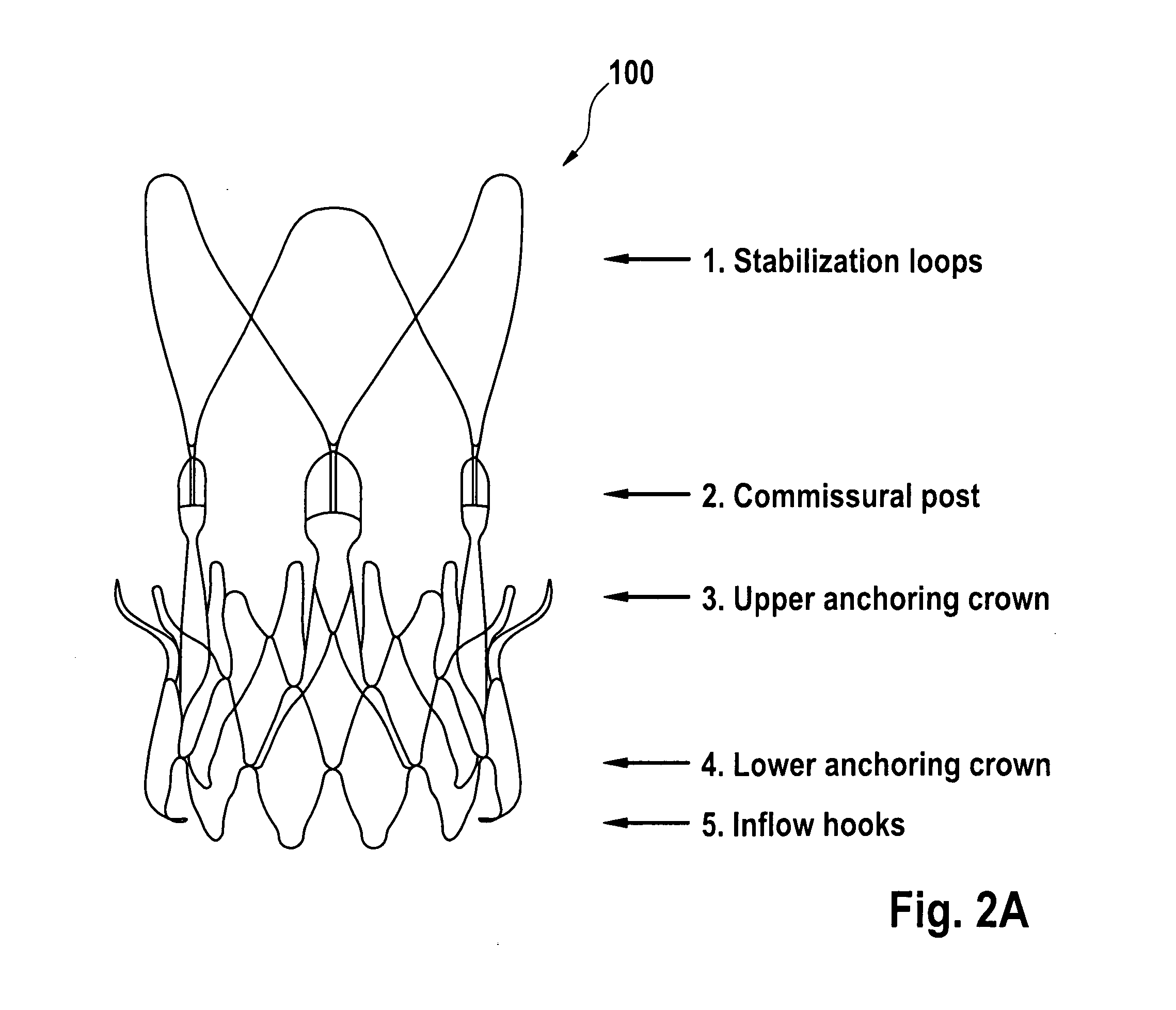
[0020]In some embodiments, the lower anchoring crown is configured to create a form fit with an inflow of an aortic valve and thus prevent migration of the stent component and the valve component towards the ascending aorta.
[0021]In some embodiments, the upper anchoring crown is configured to create a form fit with an outflow tract and native leaflets of an aortic valve and thus prevent migration of the stent component and the valve component towards the left ventricle.
[0022]In some embodiments the tips of the upper anchoring crown may rest in a final position on or against the pushed back native valve leaflets and thus prevent migration of the stent component and the valve component towards the ascending aorta and / or towards the left ventricle.
[0025]In some embodiments, the stabilization arches or loops are configured to engage the ascending aorta to orient the stent component, the valve component, and an associated delivery system longitudinally within an aorta / aortic annulus thus preventing tilting of the stent component and the valve component during the implantation procedure and / or when implanted.
[0033]In some embodiments of the present disclosure, a stent component may be provided that includes a central, longitudinal axis and at least one attachment element for removable attachment to a delivery device. The at least one attachment element may be formed generally in the shape of a hook extending inwardly towards the central, longitudinal axis. The delivery device may include a stent holder comprising a groove for receiving the attachment element of the stent component, where release of the stent-valve from the stent holder may be facilitated by rotation of the stent holder relative to the attachment element.
[0051]The inner member and the outer member are co-axially positioned and slidable relative to one another in order to transition from a closed position to an open position, such that in the closed position the sheath encompasses at least a portion of the stent-valve still attached to the stent holder constraining expansion of the stent-valve, and such that in the open position the outer sheath does not constrain expansion of the stent-valve and the stent-valve detaches from the stent holder and expands to an expanded configuration. The release of the stent-valve from the stent holder may optionally be facilitated by slight rotation and / or axial movement of the stent holder relative to the attachment element.

Problems solved by technology

While less invasive and arguably less complicated, percutaneous heart valve replacement therapies (PHVT) still have various shortcomings, including the inability for a surgeon to ensure proper positioning and stability of the replacement valve within the patient's body.
Specifically, if the replacement valve is not placed in the proper position relative to the implantation site, it can lead to poor functioning of the valve.
For example, in an aortic valve replacement, if the replacement valve is placed too high, it can lead to valve regurgitation, instability, valve prolapse and / or coronary occlusion.
If the valve is placed too low, it can also lead to regurgitation and mitral valve interaction.
While such systems may address the problem of improper placement, they are somewhat complicated, requiring the use of wires which are removable attached to an end of the stent to pull the stent back into the delivery catheter.

Method used


Image

  • Aortic bioprosthesis and systems for delivery thereof
  • Aortic bioprosthesis and systems for delivery thereof
  • Aortic bioprosthesis and systems for delivery thereof

Examples


Embodiment Construction

[0074]Some embodiments of the present disclosure are directed to systems, methods, and devices for cardiac valve replacement. For example, such methods, systems, and devices may be applicable to the full range of cardiac-valve therapies including, for example, replacement of failed aortic, mitral, tricuspid, and pulmonary valves. Some embodiments may facilitate a surgical approach on a beating heart without the need for an open-chest cavity and heart-lung bypass. This minimally-invasive surgical approach may reduce the risks associated with replacing a failed native valve in the first instance, as well as the risks associated with secondary or subsequent surgeries to replace failed artificial (e.g., biological or synthetic) valves.

Stents, Stent-Valves / Valved-Stents

[0075]Some embodiments of the present disclosure relate to stents and stent-valves or valved-stents. Valved-stents according to some embodiments of the present disclosure may include a valve component and at least one sten...


PUM


Abstract

Embodiments of the present disclosure are directed to stents, valved-stents, and associated methods and systems for their delivery via minimally-invasive surgery.

Description

FIELD OF THE DISCLOSURE[0001]Embodiments of the present disclosure are directed to systems, methods, and devices for cardiac valve replacement in mammalian hearts.BACKGROUND OF THE DISCLOSURE[0002]Conventional approaches for cardiac valve replacement require the cutting of a relatively large opening in the patient's sternum (“sternotomy”) or thoracic cavity (“thoracotomy”) in order to allow the surgeon to access the patient's heart. Additionally, these approaches require arrest of the patient's heart and a cardiopulmonary bypass (i.e., use of a heart-lung bypass machine to oxygenate and circulate the patient's blood). In recent years, efforts have been made to establish a less invasive cardiac valve replacement procedure, by delivering and implanting a cardiac replacement valve via a catheter percutaneously (i.e., through the skin) via either a transvascular approach—delivering the new valve through the femoral artery, or by transapical route, where the replacement valve is delivere...

Claims


Application Information

Patent Timeline
IPC IPC(8): A61F2/06A61F2/84
CPCA61F2/2412A61F2/2418A61F2230/0054A61F2220/0058A61F2/2436
Inventor ESSINGER, JACQUESBIADILLAH, YOUSEFFDELALOYE, STEPHANEHEFTI, JEAN-LUCMANTANUS, LUCPASSERINI, REYNALD
Owner BOSTON SCI LTD
Learn More