Optical system, barrel, and optical instrument using same

a technology of optical systems and barrels, applied in the direction of mountings, instruments, coatings, etc., can solve the problems of deterioration of imaging performance of optical systems, and deterioration of anti-reflection properties, so as to achieve excellent environmental resistance and suppress the effect of reducing imaging performan

Active Publication Date: 2012-11-01
CANON KK
View PDF6 Cites 12 Cited by
  • Summary
  • Abstract
  • Description
  • Claims
  • Application Information

AI Technical Summary

Benefits of technology

[0006]Accordingly, the present invention provides an optical system and a barrel that suppress the reduction in imaging performance and exhibit excellent environmental resistance.

Problems solved by technology

However, although the multilayer film may exhibit high anti-reflection properties with respect to light beam of the wavelength and the incidence angle used in the design phase, it is difficult for the multilayer film to maintain high anti-reflection properties over a wide wavelength band and a wide incidence angle.
However, in the optical system disclosed in Japanese Patent Laid-Open No. 2005-157119, there is no description of a method for assembling a lens (optical element) having a fine concave-convex feature to a barrel within the interior of the optical system.
Consequently, the lens is distorted, resulting in deterioration of the imaging performance of the optical system.
However, when an adhesive is used, the components contained therein such as a solvent or a monomer may be evaporated or blown away depending on the type of the adhesive.
Hence, when such adhesive is used in a sealed space such as the interior of a barrel, a lens may be fogged after being assembled, resulting in deterioration of anti-reflection properties.

Method used


Image

  • Optical system, barrel, and optical instrument using same
  • Optical system, barrel, and optical instrument using same
  • Optical system, barrel, and optical instrument using same

Examples


first embodiment

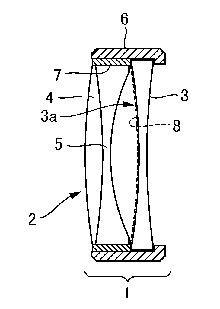
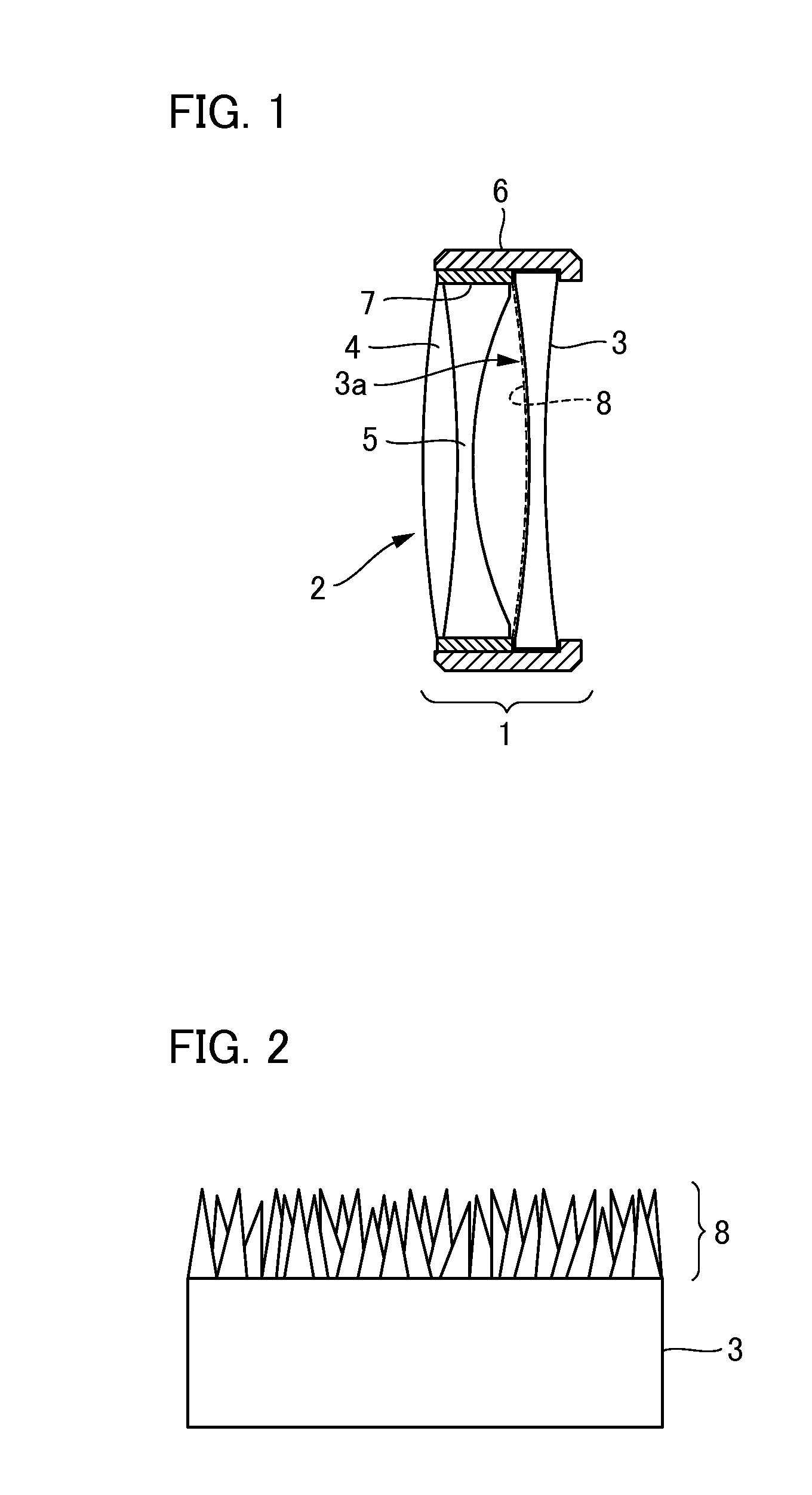
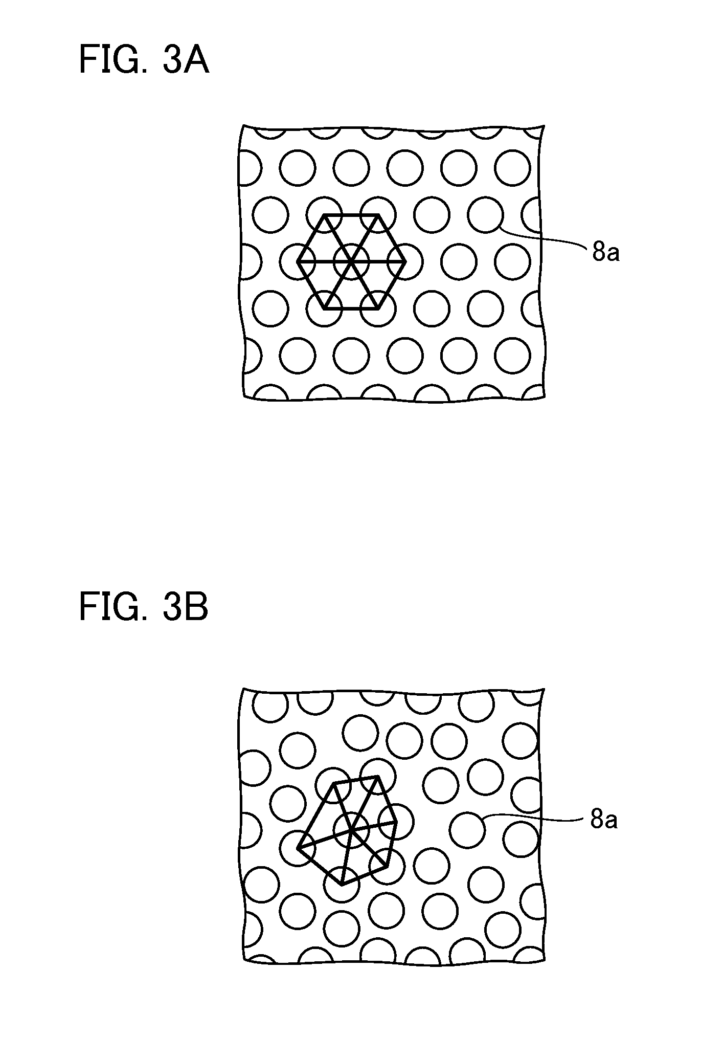
[0017]Firstly, a description will be given of an optical system according to a first embodiment of the present invention. FIG. 1 is a schematic cross-sectional view illustrating the configuration of an optical system 1 according to the first embodiment of the present invention. The optical system 1 is a lens (optical element) unit provided in an imaging apparatus such as a camera or the like or a focusing optical system constructed inside a lens barrel. The optical system 1 has at least two or more lenses arranged in the optical-axis direction. In particular, in the present embodiment, the optical system 1 includes a first lens 2 which is a joined lens and a second lens 3 having an anti-reflection film in sequence from the side where light is incident.

[0018]The first lens 2 consists of a double-convex lens 4 on the light entrance side and a double-concave lens 5 on the light exit side, which are joined together. For example, the double-concave lens 5 has a lens outer diameter “D” of...

second embodiment

[0025]Next, a description will be given of an optical system according to a second embodiment of the present invention. In the first embodiment, an epoxy-type UV-curable resin is used singularly as an energy-curable resin, whereas a feature of the optical system of the present embodiment lies in the fact that an epoxy-type UV-curable resin and acrylic UV-curable resin are used in combination as an energy-curable resin. FIG. 4 is a schematic cross-sectional view illustrating the configuration of the optical system 10 according to the present embodiment. As in the first embodiment, the optical system 10 has at least two or more lenses arranged in the optical-axis direction. The optical system 10 includes a first lens 11 which is a combination of two lenses and a second lens 12 having an anti-reflection film in sequence from the side where light is incident. As in the second lens 3 of the first embodiment, the second lens 12 of the present embodiment is a double-concave lens having the...


PUM

PropertyMeasurementUnit
viscosityaaaaaaaaaa
heightaaaaaaaaaa
heightaaaaaaaaaa

Abstract

Provided is an optical system having at least two or more lenses, wherein at least one of the lenses comprises an anti-reflection film formed by a wetting method on a part of or the entirety of the light beam effective surface thereof, and wherein at least one of the lenses other than the lens comprising the anti-reflection film is fixed to the space between the lens and a barrel for holding the lens via an energy-curable resin to be filled therein.

Description

BACKGROUND OF THE INVENTION[0001]1. Field of the Invention[0002]The present invention relates to an optical system, a barrel, and optical instrument using the same.[0003]2. Description of the Related Art[0004]Conventionally, for an optical element such as a lens or a prism for use in an imaging apparatus such as a camera or the like, an anti-reflection film for preventing the loss of the intensity of incident light or the occurrence of unwanted light such as flares or ghost due to reflected light is installed on the optical surface thereof. For example, for a camera lens, a multilayer film configured by stacking dielectric thin films (typically called “multi-coating”) is employed as an anti-reflection film. In the multilayer film, thin films having different refractive indices and having appropriate thicknesses are stacked, whereby the phases and the amplitudes of reflected waves generated on the surfaces (interfaces) of the films are adjusted and interfered with each other so as to...

Claims


Application Information

Patent Timeline
Patent Type & Authority Applications(United States)
IPC IPC(8): G02B1/11G02B3/00G02B1/113G02B1/118G02B7/02
CPCG02B1/115G02B2207/107G02B1/118G02B7/025
Inventor OKUNO, TAKEHARU
Owner CANON KK
Why Eureka
Try Eureka