Light module of motor vehicle for generating spot distribution of high-beam-light distribution and vehicle headlights having such module

a technology of light module and motor vehicle, which is applied in the field of light module of motor vehicle, can solve the problems of increasing thermal load in relation, difficult to manage from a light-technology perspective, and relatively high level of expenditure for matrix-type configuration known regarding development and production, so as to reduce reduce the space and weight of the light module, and reduce the effect of the diameter of the entire lens

Inactive Publication Date: 2012-11-01
AUTOMOTIVE LIGHTING REUTLINGEN GMBH
View PDF1 Cites 83 Cited by
  • Summary
  • Abstract
  • Description
  • Claims
  • Application Information

AI Technical Summary

Benefits of technology

[0057]As a result of the special shape of the lens elements, they cause an expansion of the pixel, or the light-exit surface of the sub-module in the vertical plane. As a result, a clear bundling of the light emitted from the sub-module occurs. This means that the light bundles of individual sub-modules arrive at a secondary lens disposed in the light path more strongly bundled. This can, therefore, have smaller dimensions than was possible with a conventional LED matrix beam. For a secondary lens designed as a projection lens, this means that the lens-permeation surface through which the light bundles of the sub-module pass is smaller. For instance, no (or much less) light passes through the upper and lower edges of the lenses. Because the edges of a lens are responsible for the formation of color fringes in the mapping thereof, by the invention, the color fringes of the spot distribution can be significantly reduced or even nearly eliminated. In addition, it is conceivable that the projection lens be flattened at the upper and lower edges [i.e., the upper and lower-edge regions—through which, due to the stronger light bundling, no (or very little) light passes—can be removed, thus obtaining a flat-shaped secondary lens]. Alternatively, it would also be conceivable to reduce the diameter of the entire lens. By this, the necessary space and weight of the light module can be clearly reduced. Because the projection lenses can normally be seen from outside of the head

Problems solved by technology

The thermal load increases in relation to the number of chips packed closely together as well as the expenditure for establishing electrical contact to the LED chips.
A module having approximately 14 to 15 closely packed chips would require a great deal of cooling at the current state of the art and, furthermore, be difficult to manage from a light-technology perspective.
At the cost for LEDs and circuit boards (particularly, the circuitry, control, and power-control device) as well as the cooling of the LEDs, there is a relatively high level of e

Method used


Image

  • Light module of motor vehicle for generating spot distribution of high-beam-light distribution and vehicle headlights having such module
  • Light module of motor vehicle for generating spot distribution of high-beam-light distribution and vehicle headlights having such module
  • Light module of motor vehicle for generating spot distribution of high-beam-light distribution and vehicle headlights having such module

Examples


Embodiment Construction

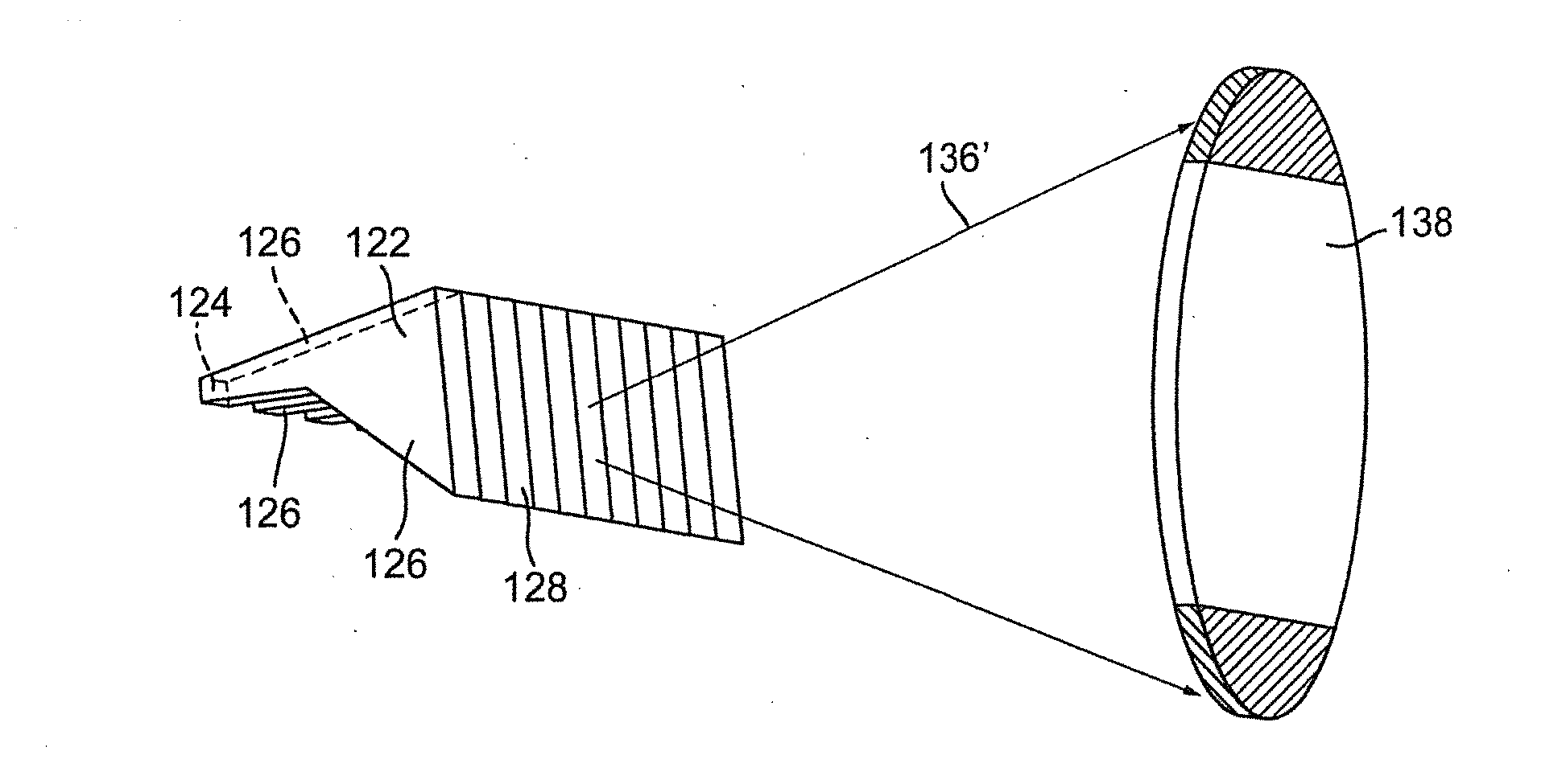
[0099]The invention concerns, in general, a light module for creating a high-beam spot and, more particularly, a spot distribution of a high-beam-light distribution. For this, a high-beam-light distribution is generated by superimposing a bundled spot beam with a diffuse, widely scattered base light. While the spot beam is more responsible for the range of the high beams, the base light provides a so-called “halo effect” [i.e., for a flat illumination around the spot beam (for instance, for a good peripheral illumination of the roadway edges and illumination above the spot beam)] to prevent a so-called “tunnel effect,” wherein, although the spot beam obtains a good distance range, the driver, due to the lack of illumination above the spot beam, has the impression of driving through a tunnel.

[0100]For this, the spot beam as well as base light can be limited to a “distance” region above a light / dark border of a low-beam-light distribution. To generate a high beam that fulfills the leg...


PUM


Abstract

A light module of a motor vehicle generates a spot distribution of a high-beam-light distribution formed by superimposition of the spot distribution and a base distribution generated by at least one other module. The light module comprises a plurality of separately controllable sub-modules that generate a plurality of stripe-shaped segments of the spot distribution that supplement it. Also, a headlight generates the high-beam-light distribution and comprises the light module. Furthermore, a headlight system comprises a pair of the headlights disposed in a front region toward sides of the vehicle and each of which generates the high-beam-light distribution. The headlights include corresponding light modules that generate stripe-shaped segments of left and right sides, respectively, of the spot distribution such that the stripe-shaped segments of the light modules of the headlights supplement the spot distribution or are at least partially superimposed thereon.

Description

CROSS-REFERENCE TO RELATED APPLICATIONS[0001]This application claims priority to and benefit of the filing date of German Patent Application 10 2011 017 630.6 filed on Apr. 27, 2011 and German Patent Application 10 2011 077 636.2 filed on Jun. 16, 2011.BACKGROUND OF INVENTION[0002]1. Field of Invention[0003]The invention concerns a light module of a motor vehicle. The light module serves to generate a spot distribution of a high-beam-light distribution. The high-beam-light distribution is formed by a superimposition of the spot distribution and a base distribution generated by at least one other module. The invention also concerns a motor-vehicle headlight for generating a high-beam-light distribution. The headlight includes a light module designed for generating a spot distribution of the high-beam-light distribution. The high-beam-light distribution is formed by a superimposition of the spot distribution and a base distribution generated by at least one other module. Finally, the ...

Claims


Application Information

Patent Timeline
IPC IPC(8): B60Q1/04
CPCB60Q1/1423B60Q2300/056G02B6/0008F21S48/1241F21S48/1747F21S48/1154F21S41/143F21S41/151F21S41/24F21S41/663
Inventor HAMM, MICHAELROSENHAHN, ERNST-OLAFSTEFANOV, EMIL P.
Owner AUTOMOTIVE LIGHTING REUTLINGEN GMBH
Why Eureka
Try Eureka