Object Detection and Position Determination by Reflected Global Navigation Satellite System Signals

a global navigation satellite and signal technology, applied in the field of object detection and position determination, can solve the problems of affecting the accuracy of the code coordinates determined by the navigation receiver, and not taking into account the reflection of the general environmen

Active Publication Date: 2012-11-01
TOPCON POSITIONING SYST INC
View PDF3 Cites 17 Cited by
  • Summary
  • Abstract
  • Description
  • Claims
  • Application Information

AI Technical Summary

Benefits of technology

[0009]Detection of the object and the position of the object is determined from the navigation signals reflected from the object; the position of the navigation receiver is determined from the direct navigation signals; and the navigation sig

Problems solved by technology

These reflected signals, referred to as multipath signals, degrade the accuracy of the code coordinates determined by the navigation receiver.
The des

Method used


Image

  • Object Detection and Position Determination by Reflected Global Navigation Satellite System Signals
  • Object Detection and Position Determination by Reflected Global Navigation Satellite System Signals
  • Object Detection and Position Determination by Reflected Global Navigation Satellite System Signals

Examples


Embodiment Construction

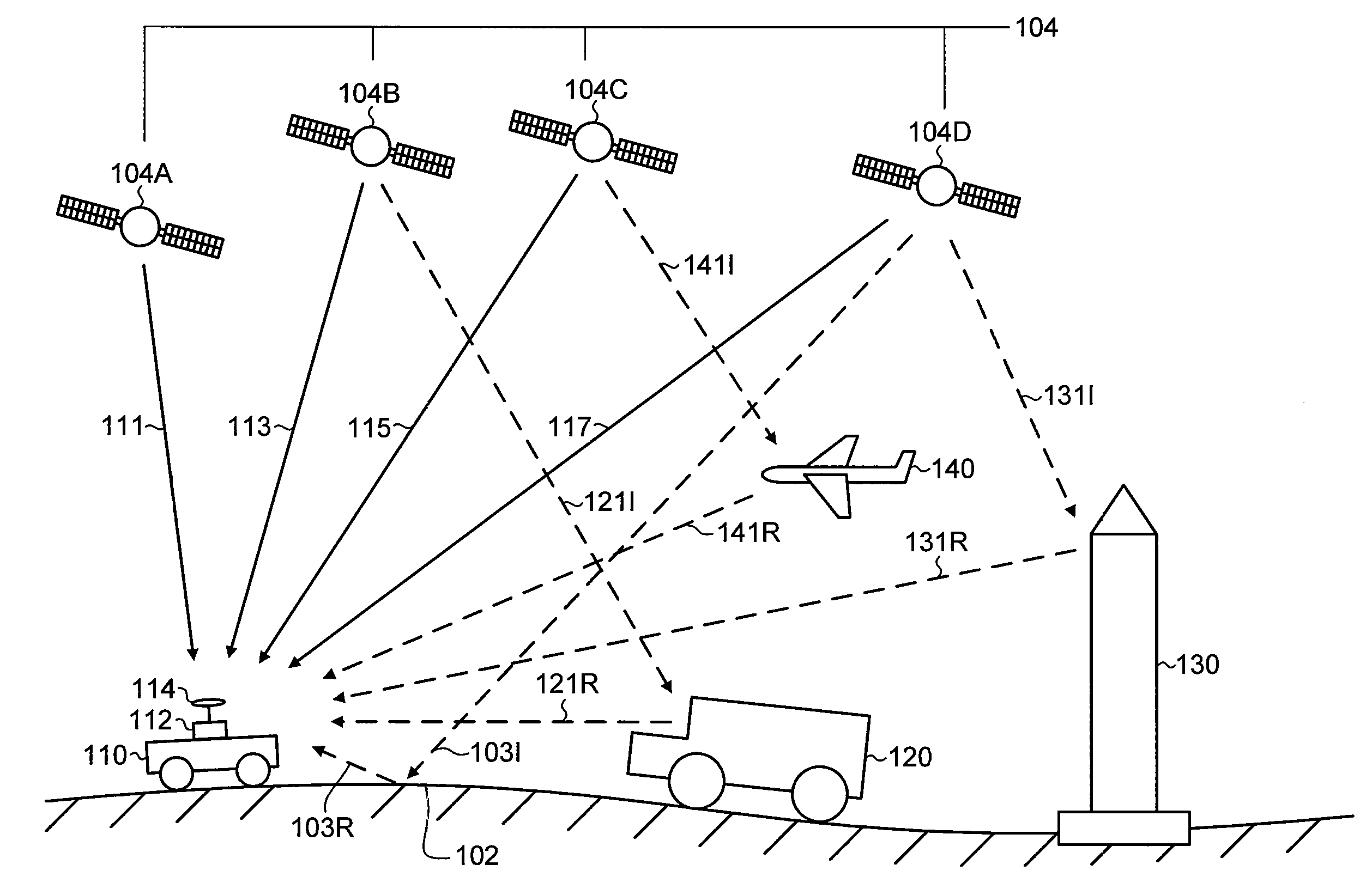
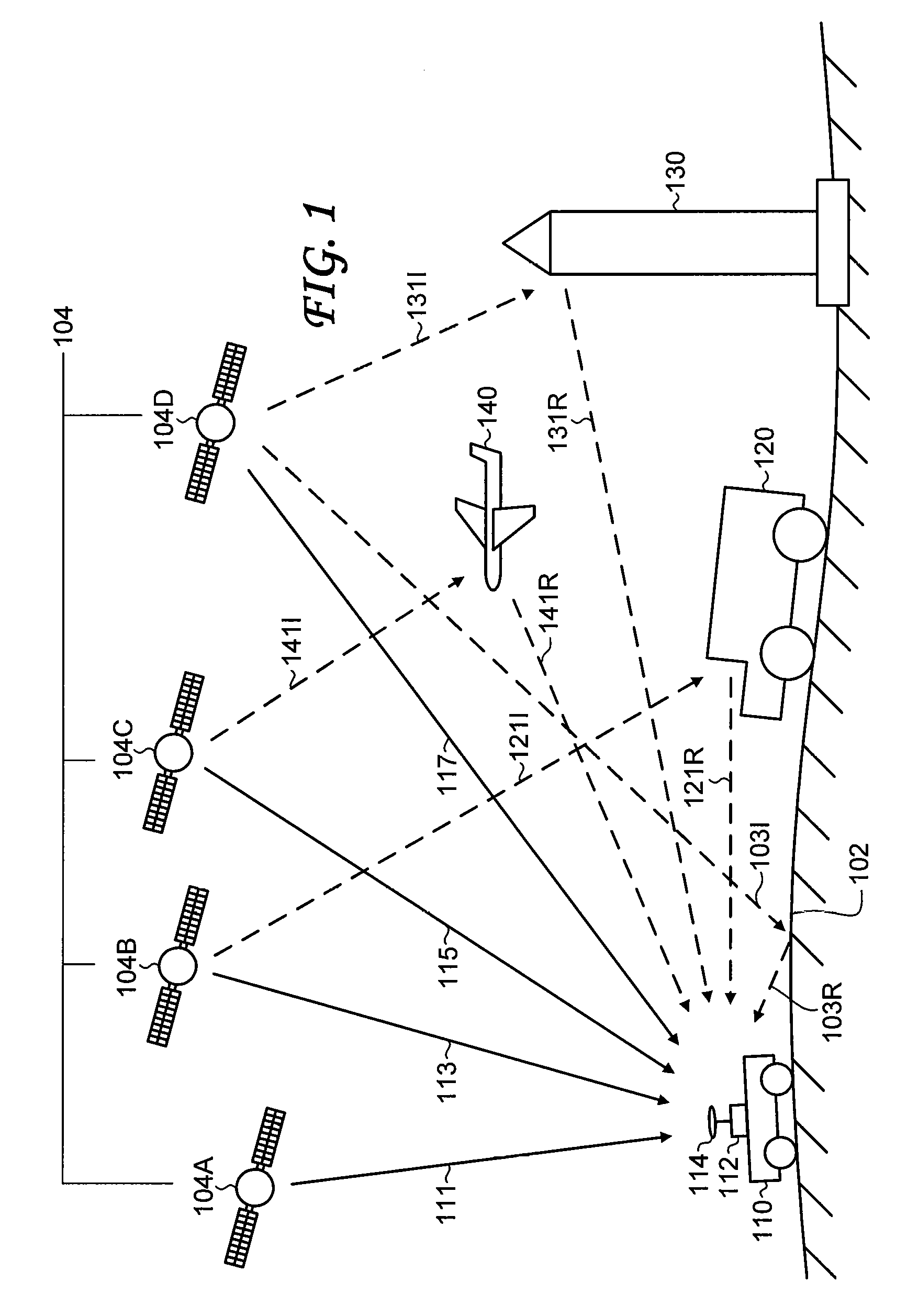
[0022]FIG. 1 shows a high-level schematic of a general signal reception environment. A constellation of global navigation satellites 104 transmits navigation signals. Shown are four representative navigation satellites, denoted navigation satellite 104A, navigation satellite 104B, navigation satellite 104C, and navigation satellite 104D. A navigation receiver 112 is outfitted with an antenna 114. The antenna 114 receives the direct navigation signal 111 from the navigation satellite 104A, the direct navigation signal 113 from the navigation satellite 104B, the direct navigation signal 115 from the navigation satellite 104C, and the direct navigation signal 117 from the navigation satellite 104D.

[0023]The navigation receiver 112 and the antenna 114 are mounted on a vehicle 110 travelling along an environmental surface 102. In the example shown in FIG. 1, the vehicle 110 is a land vehicle, such as a car or construction vehicle, and the environmental surface 102 is a ground surface. In...


PUM


Abstract

A navigation receiver mounted on a moving vehicle receives navigation signals transmitted from global navigation satellites. The navigation signals are separated into direct navigation signals, navigation signals reflected from an object, and navigation signals reflected from an environmental surface. The signal separation is based on algorithms including various combinations of signal strength, change in signal strength, delay time, spectral width, change in spectral width, and user-defined thresholds. The navigation signals reflected from an environmental surface are eliminated from further processing. The position of the navigation receiver is calculated based on the direct navigation signals. The object is detected, and the position of the object is calculated, based on the navigation signals reflected from the object. If the object is determined to lie in the path of the moving vehicle, a command can be generated to avoid collision between the moving vehicle and the object.

Description

[0001]This application claims the benefit of U.S. Provisional Application No. 61 / 479,902 filed Apr. 28, 2011, which is incorporated herein by reference.BACKGROUND OF THE INVENTION[0002]The present invention relates generally to object detection and position determination, and more particularly to object detection and position determination by reflected global navigation satellite signals.[0003]Global navigation satellite systems (GNSSs) can determine locations with high accuracy. Currently deployed GNSSs include the United States Global Positioning System (GPS) and the Russian GLONASS. Other GNSSs, such as the European GALILEO system, are under development. GNSSs are used in a wide range of applications, such as surveying, geology, and mapping.[0004]In a GNSS, a navigation receiver receives and processes radio signals transmitted by satellites located within a line-of-sight of the navigation receiver; the line-of-sight signals are referred to as direct signals. The satellite signals...

Claims


Application Information

Patent Timeline
IPC IPC(8): G08G1/16G01S19/14
CPCG01S19/22G08G1/165G01S19/14
Inventor SOSULIN, YURY G.TATARNIKOV, DMITRY V.
Owner TOPCON POSITIONING SYST INC
Why Eureka
Try Eureka