Self-reacting friction stir welding tool with the ability to add filler material

a technology of friction stir and filler material, which is applied in the direction of auxillary welding devices, furnaces, heat treatment devices, etc., can solve the problems of stress notches in the joints, increased complexity of requiring movable shoulders to increase or decrease spacing, and loss of shoulder contact on the thin side, so as to increase the weld thickness

Active Publication Date: 2012-11-08
MELD MFG CORP
View PDF3 Cites 33 Cited by
  • Summary
  • Abstract
  • Description
  • Claims
  • Application Information

AI Technical Summary

Benefits of technology

[0022]Such tooling, in contrast to existing SRFSW tooling, does not require movable shoulders because filler metal can be added to increase the weld thickness to fill the gap between the shoulders when the tooling encounters an area of the substrate where the thickness varies or the gap between the substrates changes.

Problems solved by technology

If pin depth does not extend sufficiently into the joint, the plasticized region may not extend the entire thickness of the workpiece, which may lead to stress notches in the joint.
A major drawback of SRFSW type tools are the added complexity of requiring movable shoulders to increase or decrease the spacing between the shoulders depending on the thickness of the plate being welded.
Additionally, variation in the thicknesses of plates being welded can lead to under and / or over penetration of the shoulder thus thinning the weld on the thick side and loss of shoulder contact on the thin side.

Method used


Image

  • Self-reacting friction stir welding tool with the ability to add filler material
  • Self-reacting friction stir welding tool with the ability to add filler material
  • Self-reacting friction stir welding tool with the ability to add filler material

Examples


Embodiment Construction

[0031]Reference will now be made in detail to various exemplary embodiments of the invention. It is to be understood that the following discussion of exemplary embodiments is not intended as a limitation on the invention. Rather, the following discussion is provided to give the reader a more detailed understanding of certain aspects and features of the invention.

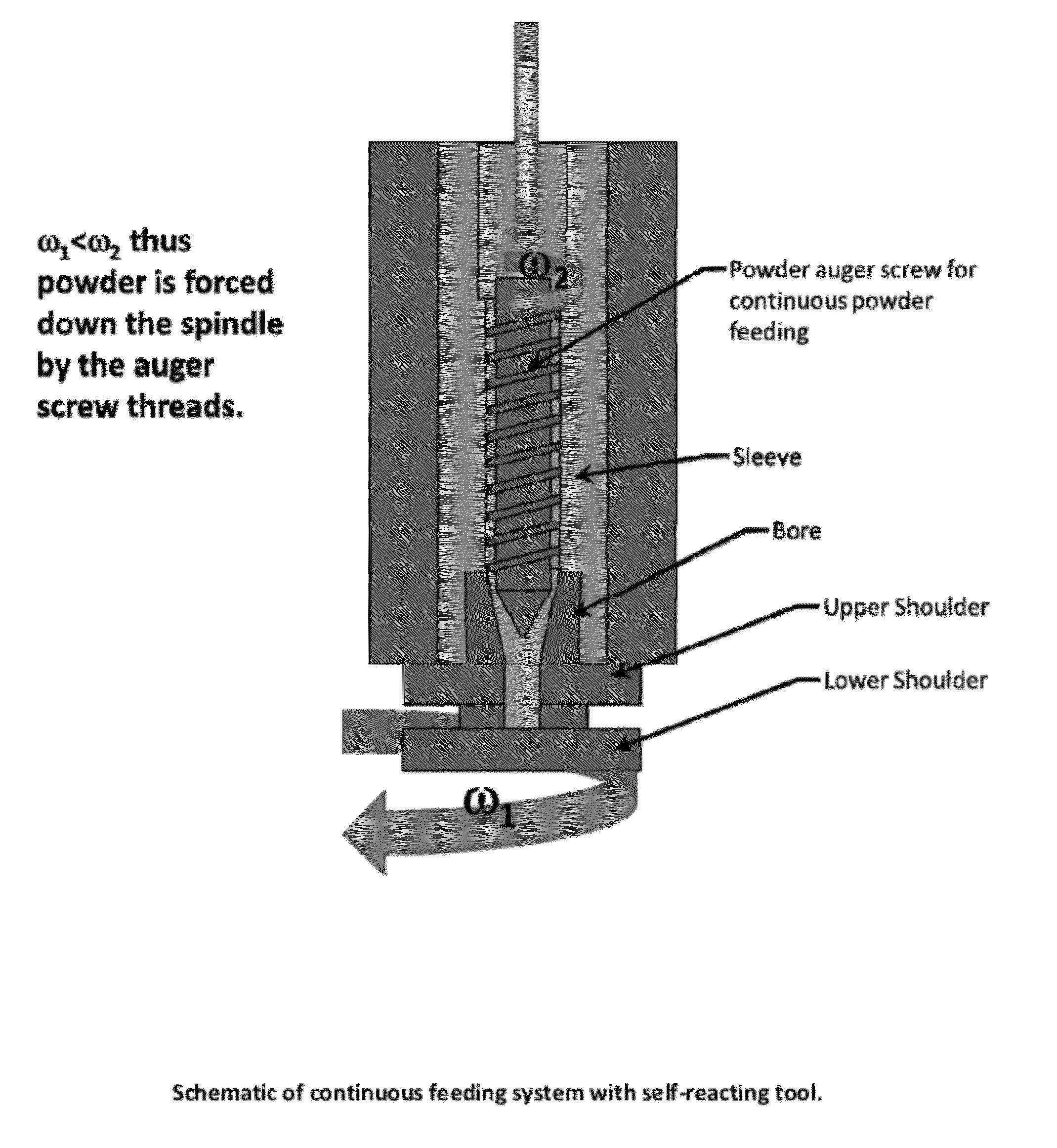
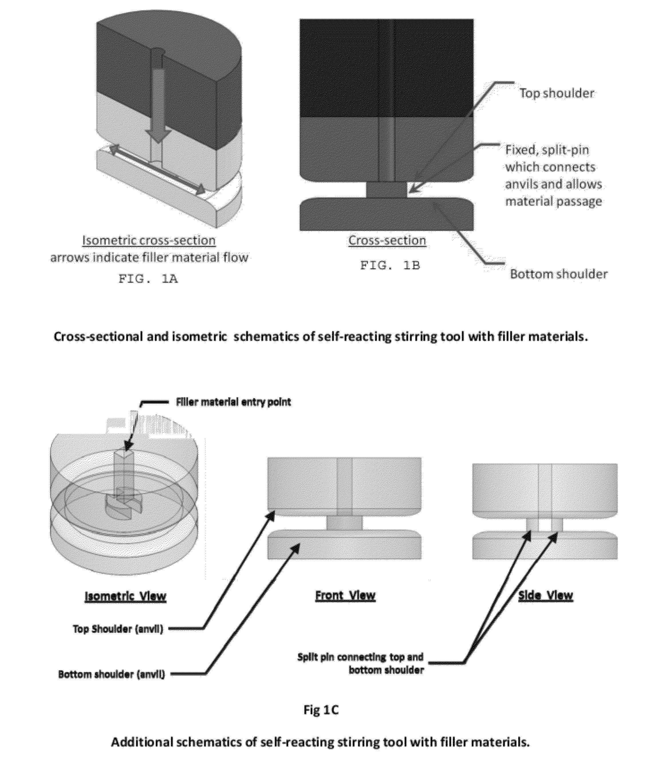
[0032]As shown in FIGS. 1A-B, consumable feed material can be introduced into the spindle of a non-consumable tool body. In embodiments, the consumable material can be transported through a channel or passageway disposed lengthwise through the tool body as indicated by the vertical arrow in FIG. 1A. This passageway or throat is generally in the form of a hollow cylinder or other similar shape to reduce drag or interference between particles passing through the channel and the walls of the channel. The throat can be the same diameter throughout the length of the tool body or the diameter can be larger at the opening of the to...


PUM

PropertyMeasurementUnit
frictionaaaaaaaaaa
volumeaaaaaaaaaa
velocityaaaaaaaaaa

Abstract

The present invention relates to tools and methods for welding, coating, repairing, or otherwise modifying the surface of a metal substrate. More specifically, embodiments of the present invention provide self-reacting friction stir welding tools which have an internal channel that allows filler materials to be added to the weld joint or otherwise friction stir processed area. Embodiments also provide friction stir tooling having upper and lower shoulders disposed at a fixed distance from one another and connected by a fixed split-pin. The tooling can be configured for automatically dispensing varying amounts of filler material into the tooling in response to variations in thickness of a substrate being processed.

Description

CROSS-REFERENCE TO RELATED APPLICATIONS[0001]This application is a Continuation-in-Part (CIP) application of U.S. application Ser. No. 12 / 792,655, filed on Jun. 2, 2010, which is a CIP of U.S. application Ser. No. 11 / 527,149, filed on Sep. 26, 2006, which claims priority to and the benefit of the filing date of U.S. Provisional Application No. 60 / 720,521, filed Sep. 26, 2005; and this application is a CIP of U.S. application Ser. No. 12 / 987,588, filed Jan. 10, 2011, which claims priority to and the benefit of the filing date of U.S. Provisional Application No. 61 / 293,543, filed Jan. 8, 2010; and this application claims priority to and the benefit of the filing date of U.S. Provisional Application Nos. 61 / 472,918 and 61 / 472,928, filed Apr. 7, 2011, and U.S. Provisional Application No. 61 / 473,221, filed Apr. 8, 2011, the disclosures of each of which is hereby incorporated by reference herein in their entireties.STATEMENT OF GOVERNMENT INTEREST[0002]This invention was supported by the ...

Claims


Application Information

Patent Timeline
Patent Type & Authority Applications(United States)
IPC IPC(8): B23K20/12C21D1/34B05C11/00
CPCB22F2998/00B23K20/1225C23C26/00C23C24/06C23C24/045B23K20/1275B23K20/128B23K2201/18B23K2203/10C21D1/34C21D9/50C21D2251/00C22C29/00C22C32/00B23K2101/18B23K2103/10
Inventor CREEHAN, KEVINSCHULTZ, JEFFREY PATRICK
Owner MELD MFG CORP
Why Eureka
Try Eureka