
Charged particle system for reticle / wafer defects inspection and review

a technology of reticle/semiconductor and charge particle, which is applied in the direction of liquid/fluent solid measurement, machines/engines, instruments, etc., can solve the problems of affecting the inspection effect of amc, and affecting the inspection effect of reticle/semiconductor

Active Publication Date: 2012-11-08
ASML NETHERLANDS BV
View PDF16 Cites 3 Cited by
  • Summary
  • Abstract
  • Description
  • Claims
  • Application Information

AI Technical Summary

Benefits of technology

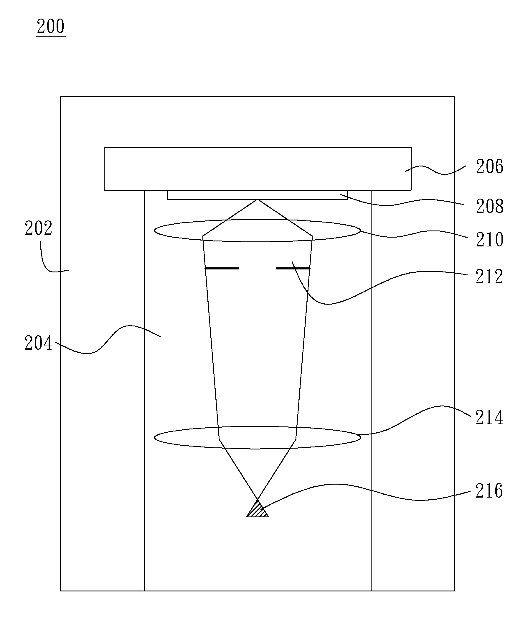
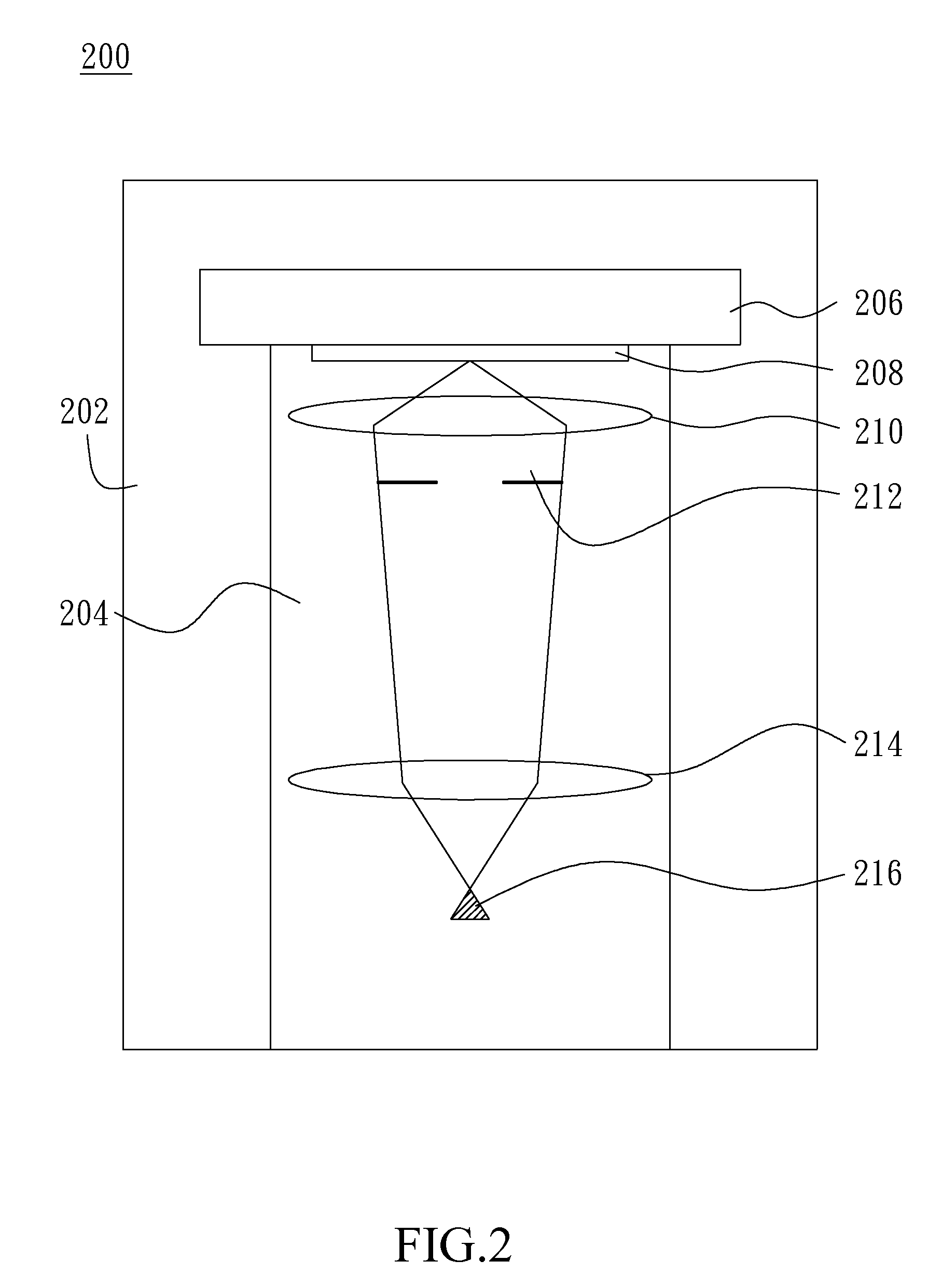
[0008]One embodiment of the present invention discloses an operation stage that sustains a face-down mounting of the inspected object on the operation stage to avoid AMC falling on inspected surface during defects inspection.
[0011]The upside down inspection system is equipped with a multi-axial lens column to gain throughput in addition to the benefit of preventing AMC contamination during inspection.

Problems solved by technology

Since a single mask can be used in production of hundreds or even thousands of wafers, therefore, an undetected error or defect in the mask can cause significant loss in yield.
A defect is called hard defect if it is not possible to be removed by a cleaning process.
Although soft defects are removable with a cleaning process, however, accidentally deposited particles on the reticle over a critical size may result in a fatal defect in every die of the wafer, corresponding to zero yield.
However because of high material absorption of this wavelength, EUV reticles do not have a protective pellicle in proximity of the surface to prevent particles from accidentally falling on the pattern area especially during handling and exposure.
In the electron beam inspection practice, no matter inspecting conventional wafers, reticles or EUV masks, no protective pellicle can be used.

Method used


Image

  • Charged particle system for reticle / wafer defects inspection and review
  • Charged particle system for reticle / wafer defects inspection and review
  • Charged particle system for reticle / wafer defects inspection and review

Examples


Embodiment Construction

[0023]Reference will now be made in detail to specific embodiments of the invention. Examples of these embodiments are illustrated in accompanying drawings. While the invention will be described in conjunction with these specific embodiments, it will be understood that it is not intended to limit the invention to these embodiments. On the contrary, it is intended to cover alternatives, modifications, and equivalents as may be included within the spirit and scope of the invention as defined by the appended claims. In the following description, numerous specific details are set forth in order to provide a thorough understanding of the present invention. The present invention may be practiced without some or all of these specific details. In other instances, well known process operations are not described in detail in order not to unnecessarily obscure the present invention.

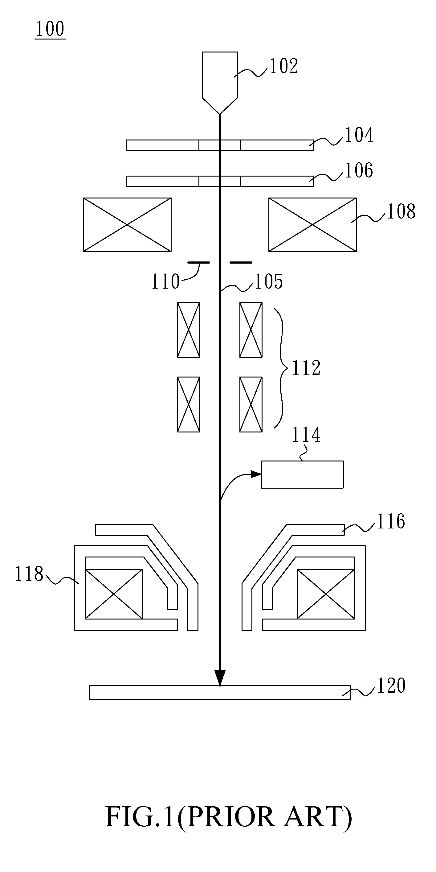
[0024]FIG. 1 is a schematic diagrammatic representation of a conventional e-beam inspection system 100. The conve...


PUM

PropertyMeasurementUnit
SEMaaaaaaaaaa
vacuumaaaaaaaaaa
electricallyaaaaaaaaaa

Abstract

The present invention relates to a charged particle system for reticle or semiconductor wafer defects inspection and review, and more particularly, relates to an E-beam inspection tool for reticle or semiconductor wafer defects inspection and review without gravitational AMC settling. The charged particle system is an upside down electron beam inspection system with an electron beam aimed upward. The face down design may prevent AMC from gravitational settling on the inspected face of the specimen during inspection, thereafter having a cleaner result compared with conventional face-up inspection system.

Description

CROSS-REFERENCE TO RELATED APPLICATIONS[0001]This application claims the benefit of U.S. Provisional Application No. 61 / 482,084 (Att. Docket HE8536PR), filed on May 3, 2011 and entitled CHARGED PARTICLE SYSTEM FOR RETICLE / WAFER DEFECTS INSPECTION AND REVIEW, the entire contents of which are hereby incorporated by reference.FIELD OF THE INVENTION[0002]The present invention relates to a charged particle system for reticle or semiconductor wafer defects inspection and review, and more particularly, relates to an E-beam inspection tool for reticle or semiconductor wafer defects inspection and review without gravitational AMC settling. However, it would be recognized that the invention has a much broader range of applicability.BACKGROUND OF THE INVENTION[0003]Defect inspection of semiconductor wafers and reticles (masks) for IC manufacturing is an accepted production process for yield enhancement. The information obtained from a wafer defect inspection tool can be used to flag defective ...

Claims


Application Information

Patent Timeline
Patent Type & Authority Applications(United States)
IPC IPC(8): G01N23/225G21K5/10
CPCG01N23/2251G01N2223/611G01N2223/307H01J37/28H01J2237/0225H01J2237/032H01J37/04H01J2237/2817
Inventor KUAN, CHIYANWANG, YI-XIANGPAN, CHUNG-SHIHDONG, ZHONGHUACHEN, ZHONGWEI
Owner ASML NETHERLANDS BV
Learn More