Mechanical energy storage method and device

a technology of energy storage and mechanical devices, applied in the direction of machines/engines, electric generator control, greenhouse gas reduction, etc., can solve the problems of unsuitability the rapid release of energy from falling objects is generally unsuitable for any known or viable commercial energy application, etc., to achieve efficient and usable energy, improve applicability and sustainability

Inactive Publication Date: 2012-11-08
HUANG HENRY C +1
View PDF5 Cites 22 Cited by
  • Summary
  • Abstract
  • Description
  • Claims
  • Application Information

AI Technical Summary

Benefits of technology

[0009]These efficient energy storage mechanisms resolve some of the problems associated with unlimited energy sources, making them less vulnerable to changing environmental conditions, and improving the applicability and sustainability of the energy generation systems that convert the limited energy sources. According to one aspect, provided is a mechanical energy storage device that operates using the principles of lifting an energy storing mass in a fashion similar to a crane lifting a heavy object. A large weight is used as the mass, and is lifted slowly from ground zero (zero potential energy) to a certain height (positive potential energy), thus creating stored energy. When the weight is released under proper control, the gravitational force pulling down on the mass causes the system to produce energy by rotating a generator. Controlling the fall so that the discharge produced occurs over long periods of time results in efficient and usable energy storage and discharge.

Problems solved by technology

It is realized that there are a number of issues to address in any system configured to produce and store energy.
However, the rapid release of energy from a falling object is generally unsuitable to any known or viable commercial energy application.

Method used


Image

  • Mechanical energy storage method and device
  • Mechanical energy storage method and device
  • Mechanical energy storage method and device

Examples


Embodiment Construction

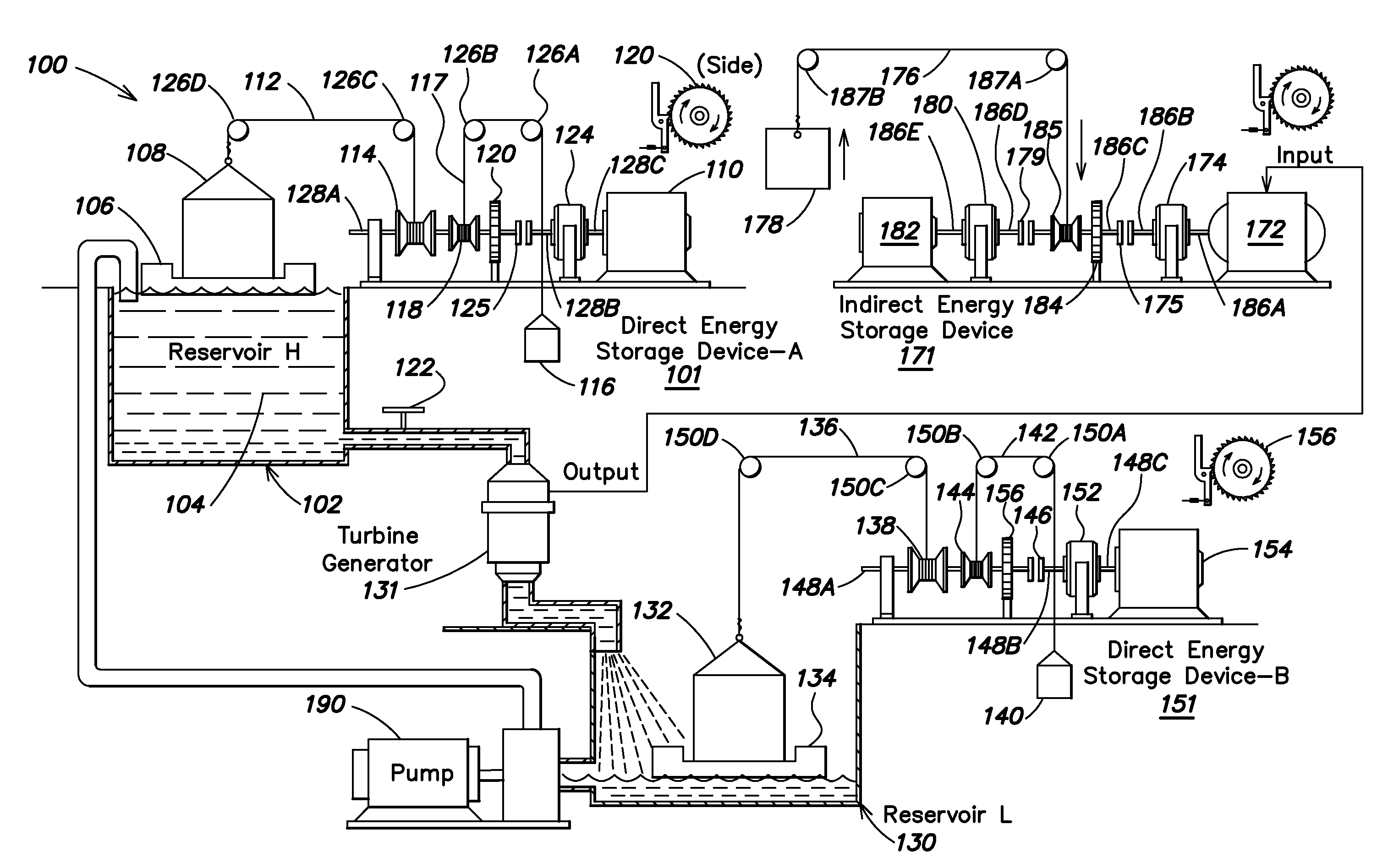
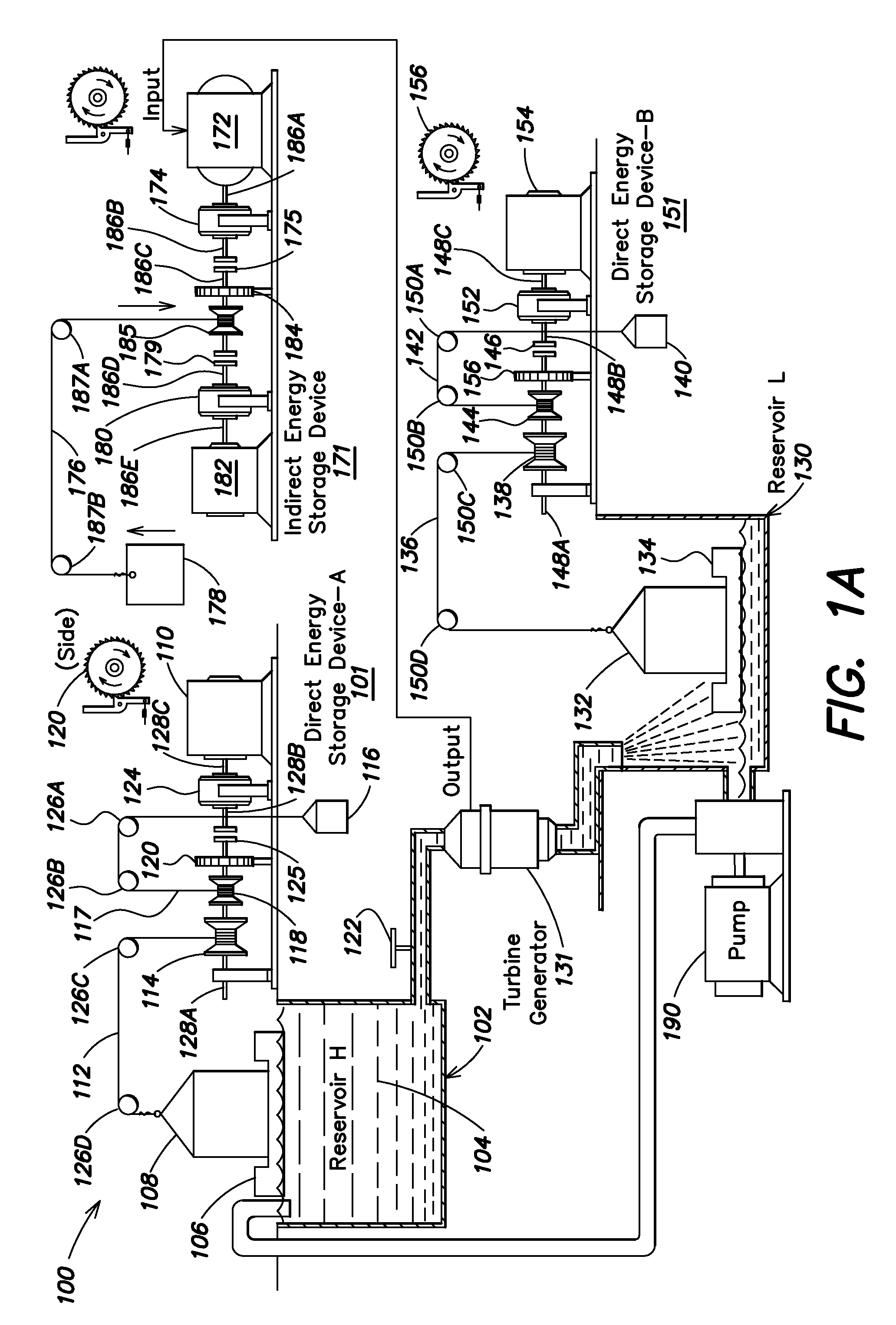
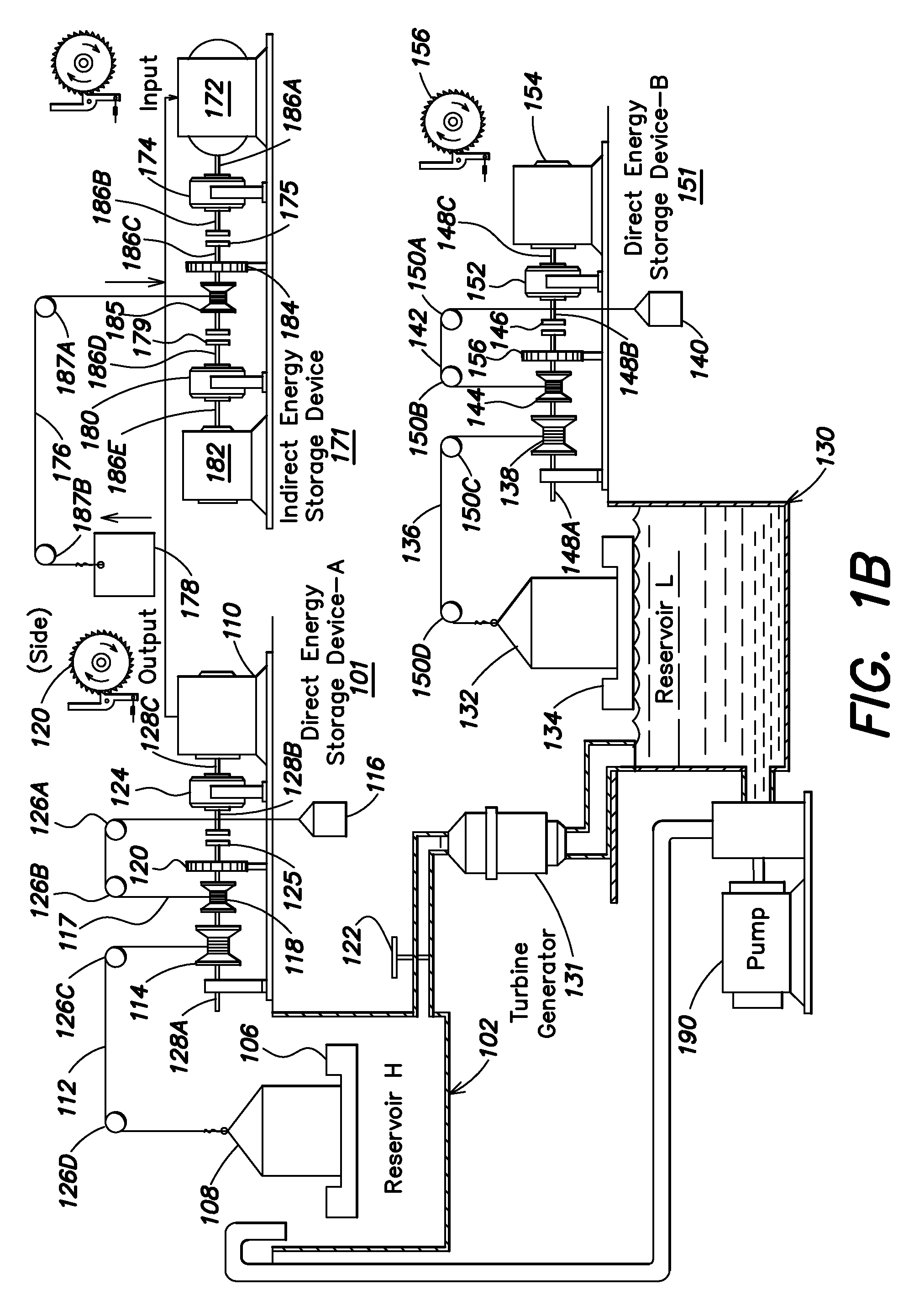
[0032]According to one aspect of the disclosure, energy storage systems that are configured to discharge over long periods of time can incorporate falling weights to achieve commercially viable energy sources. Further configuring the systems to provide a usable range of motion for the falling weights constrained by small distances ensures the usability of any energy storage systems under real world conditions. Under traditional applications, lifting an object higher results in greater potential energy. However, the ability to lift objects to greater and greater distances is necessarily constrained by physical limitations. Thus, effective energy storage systems must be able to sustain long discharge times and be physically realizable. In other words, the falling weights typically cannot move great distances.

[0033]Balancing the concerns of usable discharge time constrained by small distances has rendered previous energy storage / generation systems unusable in most settings. It is reali...


PUM


Abstract

Provided is an energy storage system configured to accumulate energy for subsequent discharge. One embodiment includes an indirect energy storage assembly configured to accept energy input from a direct storage assembly. The indirect energy storage assembly includes a converter for lifting a mass, a speed reducer coupled to the converter for increasing torque provided, and a mass coupled to the speed reducer for generating potential energy when raised. In one embodiment, the direct energy storage assembly produces energy based on descent of a mass, the descent controlled by operation of a speed increaser coupled to a generator. In one example, the speed increaser provides an input:output ratio of at least 1:100. The speed increaser can be configured based on parameters of the generator (e.g., speed and torque). The mass of the direct energy storage assembly can include a float for lifting the mass responsive to water level.

Description

BACKGROUND OF THE DISCLOSURE[0001]Significant activity has taken place in the field of energy generation, providing newer more efficient and cleaner sources of power. Conventional technologies are directed to harnessing various clean energy sources. Currently, attempts to capture energy from various clean sources (e.g., water, wind, and solar) are varied and far-reaching.[0002]Generally, energy sources can be divided into two categories: limited and unlimited. The limited sources, e.g., crude oil, natural gas, and coal, provide a great amount of output, and can be stored and transported conveniently with current infrastructure. For example, gasoline by itself is a good energy source and easily stored. This is in large part because of the infrastructure that has developed to refine and transport gasoline, which is a relatively compact liquid energy source. These limited sources, however, present many problems. One of the main problems is the environmental impact caused by excessive c...

Claims


Application Information

Patent Timeline
Patent Type & Authority Applications(United States)
IPC IPC(8): H02K7/10F03B13/06
CPCF03B13/06F05B2260/4031Y02E60/17Y02E10/22Y02E10/38Y02E10/20Y02E10/30Y02E60/16Y02E70/30
Inventor HUANG, HENRY C.HUANG, JANE
Owner HUANG HENRY C
Why Eureka
Try Eureka