
Smilled spline apparatus and smilling process for manufacturing the smilled spline apparatus

a technology of spline and spline teeth, which is applied in the direction of manufacturing tools, gear teeth, rod connections, etc., can solve the problems of reducing the effective face width of the prior art spline connection, and achieve the effect of maximizing the effective face width

Active Publication Date: 2012-11-08
FAIRFIELD MFG CO INC
View PDF9 Cites 6 Cited by
  • Summary
  • Abstract
  • Description
  • Claims
  • Application Information

AI Technical Summary

Benefits of technology

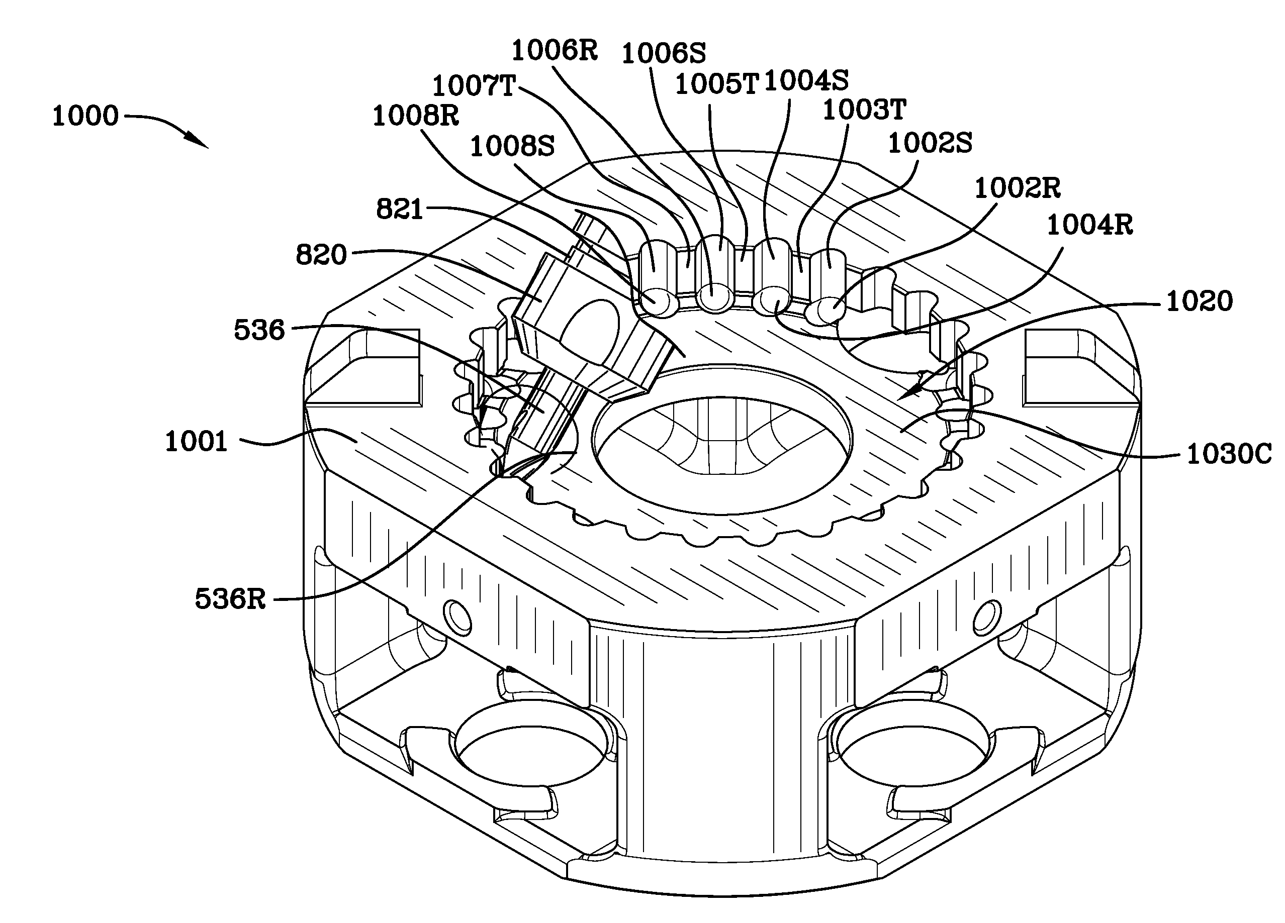
[0012]By combining shaping and milling actions, or smilling, the cutting tool can move through the entire usable portion of the spline and machine an angular relief into the face of the adjacent feature before retracting, reversing direction, and repeating the cycle. The angular relief includes a partially conically shaped portion. The smilling design and manufacturing method eliminates the need for an annular spline relief and the full length of spline engagement can be utilized for strength. The effective width of the spline connection apparatus manufactured by the smilling process conserves space and increases the load carrying capability of the spline connection.
[0018]Each of the plurality of external spline teeth of the external spline resides in a respective one of the plurality of the second tooth spaces of the internal spline. Each of the plurality of internal spline teeth of the internal spline resides in a respective one of the plurality of the first tooth spaces of the external spline. Each of the plurality of the external spline teeth of the external spline may interengage two of the plurality of the internal spline teeth and each of the plurality of internal spline teeth may interengage two of the plurality of the external spline teeth of the external spline. Each of the plurality of external spline teeth of the external spline of the male spline apparatus has a first length and each of the plurality of the internal spline teeth of the internal spline of the hub portion of the female collar apparatus has a second length equal to the first length. The first and second lengths are the effective face width, EFs, of the spline connection apparatus made by the smilling process. The entire length of the external spline engages the entire second length of the internal spline to maximize the effectiveness of the torque transfer.
[0031]It is an object of the invention is to make the smilled spline connection length shorter than a conventional spline connection using annular reliefs for the same load carrying capacity.
[0033]It is another object of the invention to increase the load carrying capacity for a given spline connection length and a given pitch diameter.
[0036]It is a further object of the present invention to eliminate annular reliefs in spline connections to maximize their effective face width and to make their effective face width (or length) equal to the spline connection length.

Problems solved by technology

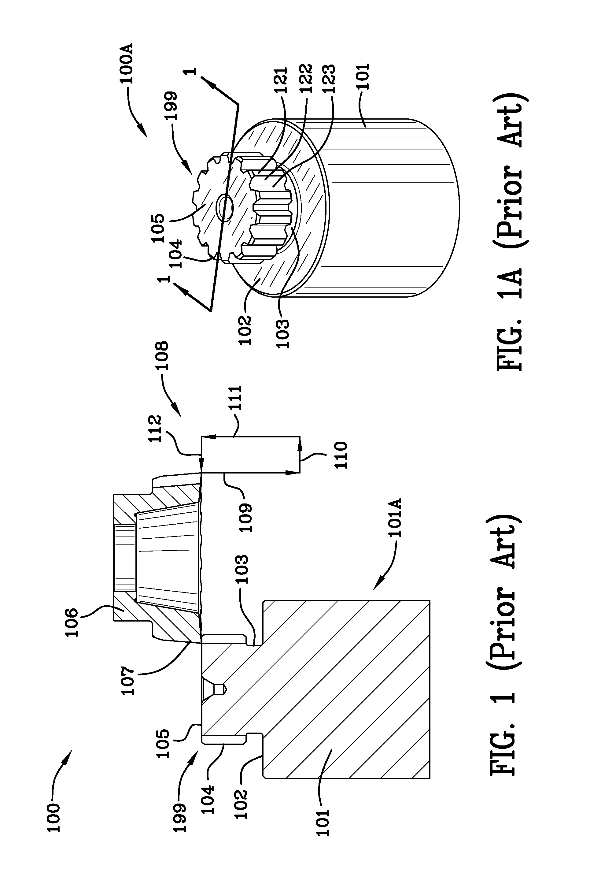
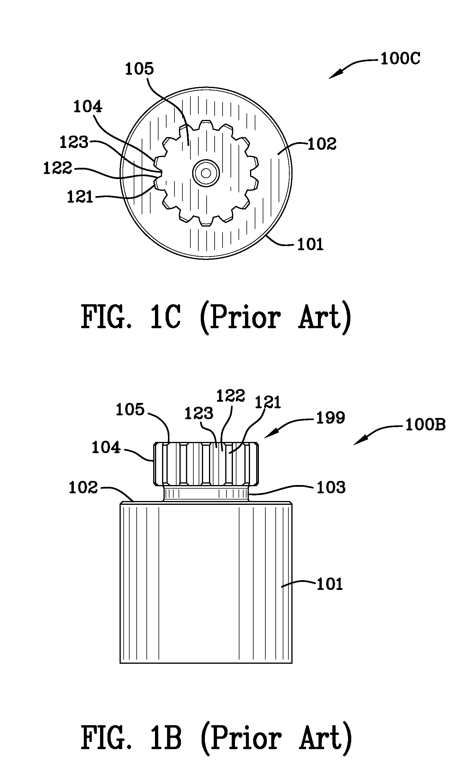
Therefore, it can be readily seen from FIG. 3 that length of the annular cutter-shaper tool reliefs reduce the effective face width of the prior art spline connection.
The problem with annular cutter-shaper tool reliefs occurs whenever splines are manufactured adjacent features.
Typically, the adjacent features are shoulders and counterbores but any adjacent feature regardless of the name applied to it will cause a problem as it will require a substantial tool relief.

Method used


Image

  • Smilled spline apparatus and smilling process for manufacturing the smilled spline apparatus
  • Smilled spline apparatus and smilling process for manufacturing the smilled spline apparatus
  • Smilled spline apparatus and smilling process for manufacturing the smilled spline apparatus

Examples


Embodiment Construction

[0082]FIG. 4 is a schematic 400 of the external and internal splines of an angular spline connection apparatus manufactured using the smilling process illustrating the pitch diameter, D, the major internal diameter, Dri, the major external diameter, Dae, the minor internal diameter, Dai, the minor external diameter, Dre, and the circular pitch, CP. FIG. 4 also illustrates the tooth thickness, TT, of the angular external teeth and the space width, SW, of the internal spline. Dfi, form internal diameter, and Dfe, form external diameter, are illustrated on FIG. 4 as are the WD, working depth, and Cr, clearance between the external spline teeth and Dri, major internal diameter.

[0083]FIG. 4A is a schematic 400A of the external and internal splines of an angular spline connection apparatus manufactured using the smilling process illustrating the external space angle, SAe, the internal tooth angle, TAi, the internal space angle, SAi, and the external tooth angle, TAe. SAe is assumed to be ...


PUM

PropertyMeasurementUnit
inclination angleaaaaaaaaaa
part space angleaaaaaaaaaa
inner circumferenceaaaaaaaaaa

Abstract

By combining shaping and milling actions, or smilling, the cutting tool can move through the entire usable portion of the spline and machine a tool relief into the face of the adjacent feature such as a shoulder before retracting, reversing direction, and repeating the cycle. The smilling apparatus and manufacturing method eliminates the need for an annular spline relief and the full length of spline engagement can be utilized for strength. The effective width of the spline connection apparatus manufactured by the smilling process conserves space and increases the load carrying capability of the spline connection.

Description

FIELD OF THE INVENTION [0001]The invention is in the field of splines having adjacent features such as shoulders and counterbore surfaces in proximity to splines.BACKGROUND OF THE INVENTION[0002]A mechanical spline is commonly used to couple a shaft and collar to transmit rotational motion and torque. If no adjacent feature such as a shoulder on the shaft or a counter bore on the collar exists, the full length of spline is engaged and can be utilized for strength and traditional manufacturing methods can be used to produce each component. However, if one or both members have adjacent features, a spline relief is required to allow for tool clearance. The length (or width) of the annular relief(s) reduce(s) the full length of spline engagement which reduces the strength of the connection proportionally. Common prior art methods of machining splines close to adjacent features include shaping and milling. Shaping involves a fixed cutting tool parallel to the spline axis, moving through ...

Claims


Application Information

Patent Timeline
Patent Type & Authority Applications(United States)
IPC IPC(8): F16B7/00B23F17/00B23F5/20
CPCB23C3/30B23C5/10B23C2265/08B23F1/04B23F1/06Y10T403/7026F16D2001/103B23F17/001B23P15/14Y10T409/105883Y10T409/103975F16D1/10
Inventor PHEBUS, DAN E.HAYWARD, WILLIAM H.
Owner FAIRFIELD MFG CO INC
Learn More