Laser welding apparatus and laser welding method

a laser welding and welding equipment technology, applied in welding/soldering/cutting articles, manufacturing tools, instruments, etc., can solve the problem that the known laser welding apparatus cannot evaluate a welded part with high accuracy, and achieve the effect of high accuracy

Active Publication Date: 2012-11-15
PANASONIC CORP
View PDF7 Cites 89 Cited by
  • Summary
  • Abstract
  • Description
  • Claims
  • Application Information

AI Technical Summary

Benefits of technology

[0009]According to the embodiments, the penetration depth of the welded part can be directly detected. Thus, the embodiments can evaluate the welded part with high accuracy. The embodiments are further applicable to laser welding on an automobile, an electronic component, and so on.

Problems solved by technology

Unfortunately, the known laser welding apparatus cannot evaluate a welded part with high accuracy.

Method used


Image

  • Laser welding apparatus and laser welding method
  • Laser welding apparatus and laser welding method
  • Laser welding apparatus and laser welding method

Examples


first embodiment

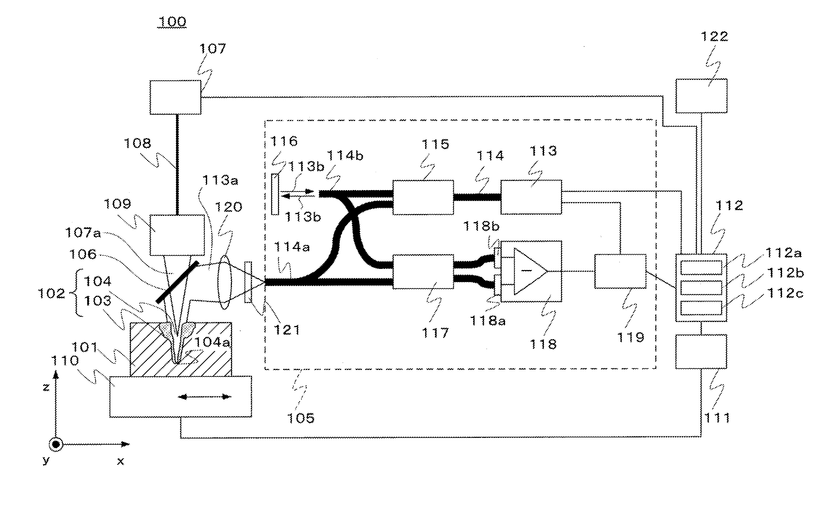
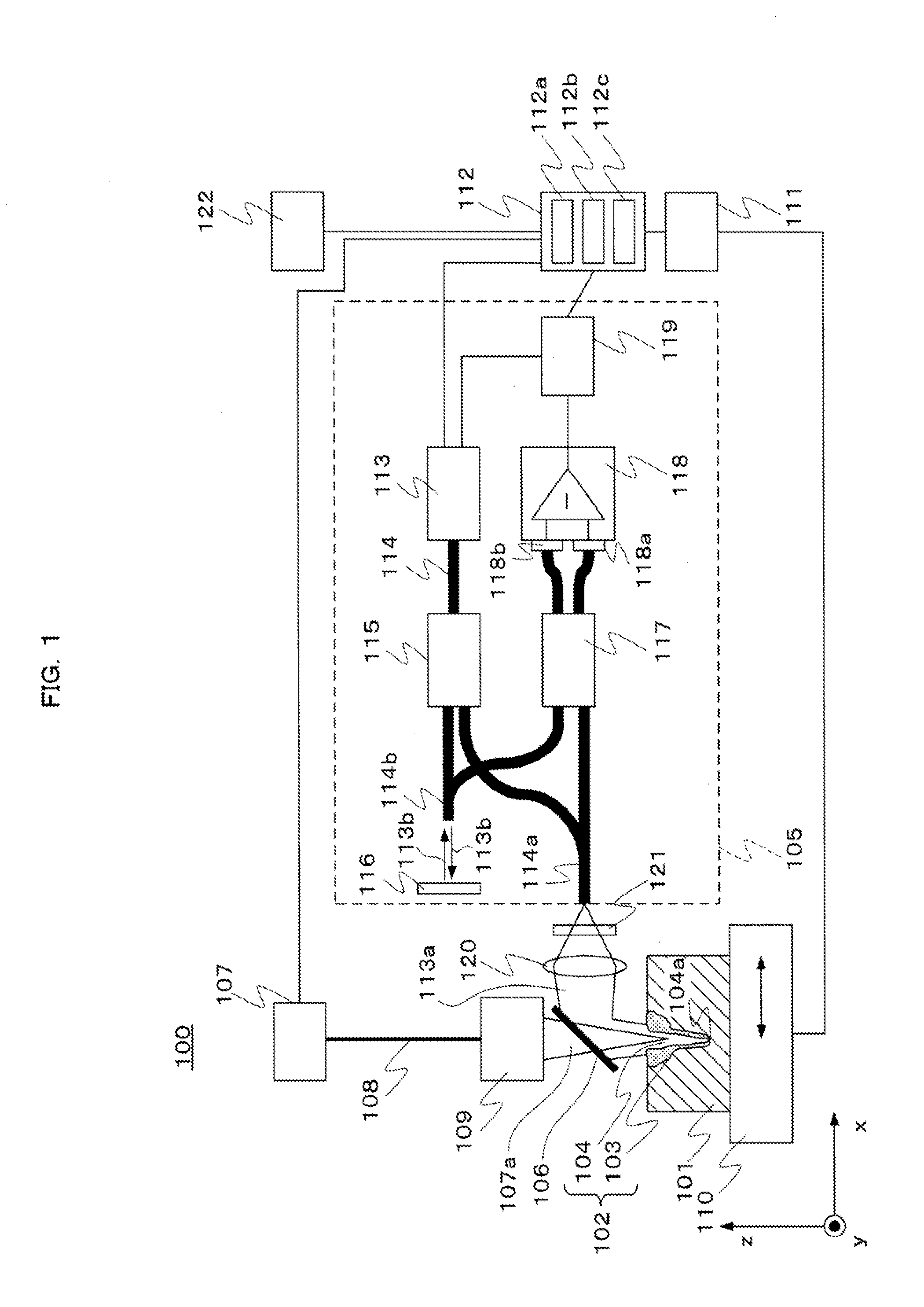
[0020]FIG. 1 is a schematic diagram illustrating a laser welding apparatus 100 according to a first embodiment. The outline of the laser welding apparatus 100 will be first discussed below.

[0021]As illustrated in FIG. 1, in the laser welding apparatus 100, a laser beam 107a is emitted from a laser oscillator 107, which is an example of a laser light source, during welding on a workpiece 101 that extends in the horizontal direction (x direction in FIG. 1). The laser beam 107a is emitted perpendicularly (z direction in FIG. 1) to the surface of the workpiece 101. Thus, a part to be welded (the same portion as a welded part 102) of the workpiece 101 melts from the top so as to form a molten pool 103 on the welded part 102. Moreover, molten metal evaporates from the molten pool 103 during the melting of the welded part 102. The pressure of steam generated by the evaporation forms a keyhole 104. In this case, the molten pool 103 and the keyhole 104 constitute the welded part 102.

[0022]Fu...

second embodiment

[0087]In the first embodiment, the spot 113c of the object beam 113a is circular. In a second embodiment, an object beam 113a has a linear spot 113c. A different point from the first embodiment will be discussed below and the explanation of the same point is omitted.

[0088]In a laser welding apparatus 200 according to the second embodiment, a second optical condenser system 120 in FIG. 1 is a cylindrical lens. Thus, the spot 113c of the object beam 113a focused on a welded part102 is a linear spot.

[0089]FIG. 7 is a plan view of the welded part 102 viewed in the vertical direction (z direction) as in FIG. 3. FIG. 7 shows the positional relationship between a spot 107b of a laser beam 107a, the spot 113c of the object beam 113a, a keyhole 104, and a molten pool 103 in the case where the second optical condenser system 120 is a cylindrical lens. A movable stage 110 on which a workpiece 101 is fixed moves in a moving direction (x direction) indicated by an arrow in FIG. 7.

[0090]As illust...

third embodiment

[0097]FIG. 8 is a schematic diagram illustrating the configuration of the main part of a laser welding apparatus 300 according to a third embodiment. The third embodiment will describe the laser welding apparatus 300 including a spectroscope 123 that calculates the optical spectrum of light 102a emitted from a welded part 102 and a material specifying unit 112d that specifies the material of the welded part 102 from the calculated optical spectrum. A different point from the first embodiment will be discussed below and the explanation of the same point is omitted.

[0098]A workpiece 101 may have regions of different materials. When laser welding is shifted from one region to another region made of a different material during welding on the workpiece 101, the welding conditions need to be changed. In the case of unknown distribution of regions of different materials, the timing of changing the welding conditions cannot be determined beforehand. Furthermore, in the case of unknown mater...


PUM

PropertyMeasurementUnit
wavelengthaaaaaaaaaa

Abstract

A laser welding apparatus includes: a first optical element that coaxially emits, to a welded part, a laser beam emitted from a laser light source and an object beam having a different wavelength from the laser beam; a second optical element that causes the spot diameter of the object beam to be larger than the spot diameter of the laser beam on the welded part; an optical interferometer that emits the object beam to the first optical element, detects through the first optical element the object beam reflected on the welded part, and generates an electric signal based on the detected object beam; and a measuring unit that measures a penetration depth of the welded part based on the electric signal.

Description

CROSS REFERENCE TO RELATED APPLICATIONS[0001]The disclosure of Japanese Patent Application No. 2011-104981 filed May 10, 2011 including specification, drawings and claims is incorporated herein by reference in its entirety.TECHNICAL FIELD[0002]The present invention relates to a laser welding apparatus and a laser welding method which weld a part to be welded by a laser beam and evaluate the welded part.BACKGROUND ART[0003]Japanese Patent Laid-Open No. 3-207587 discloses a laser welding apparatus that evaluates the quality of a welded part by means of light emanating from the molten metal of the welded part. Referring to FIG. 9, the laser welding apparatus will be described below.[0004]As illustrated in FIG. 9, the laser welding apparatus welds a workpiece 1 by irradiating the workpiece 1 with a laser beam 3. The laser beam 3 is continuously emitted with a constant intensity from a laser oscillator 11. The laser beam 3 emitted from the laser oscillator 11 is transmitted to an optical...

Claims


Application Information

Patent Timeline
Patent Type & Authority Applications(United States)
IPC IPC(8): B23K26/20B23K26/00B23K26/21G01B11/22
CPCB23K26/032B23K26/083B23K26/26B23K31/125G01B9/02069G01B11/22G01B9/02004G01B9/02091B23K2201/18B23K2101/18
Inventor URASHIMA, TAKASHIAOKI, SHOHEIKABETANI, YASUHIRO
Owner PANASONIC CORP
Why Eureka
Try Eureka