

Ultrasonic Vibration Device
- Summary
- Abstract
- Description
- Claims
- Application Information
AI Technical Summary
Benefits of technology
Problems solved by technology
Method used
Image

Examples
first embodiment
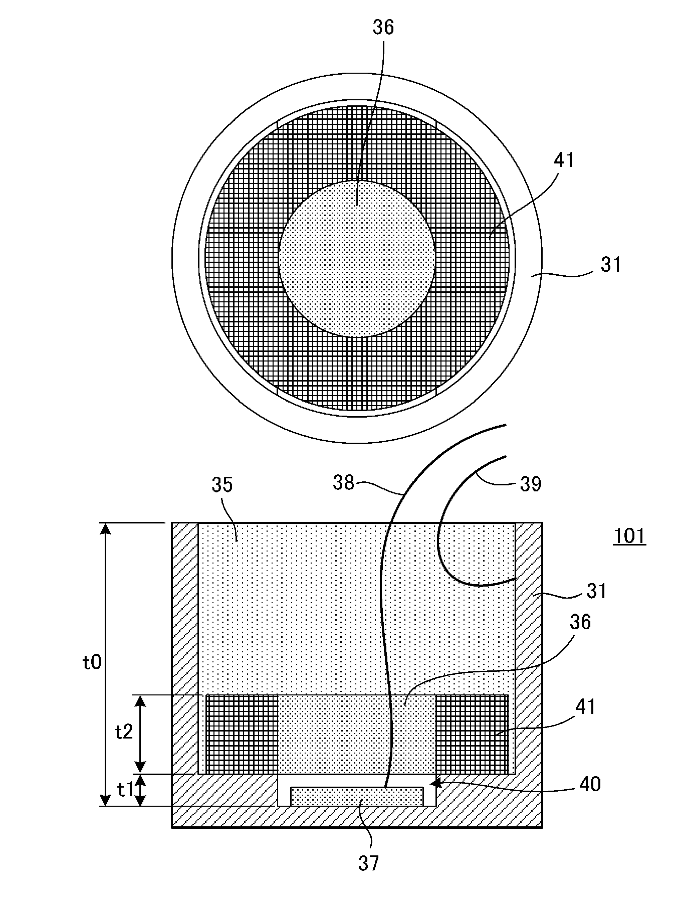
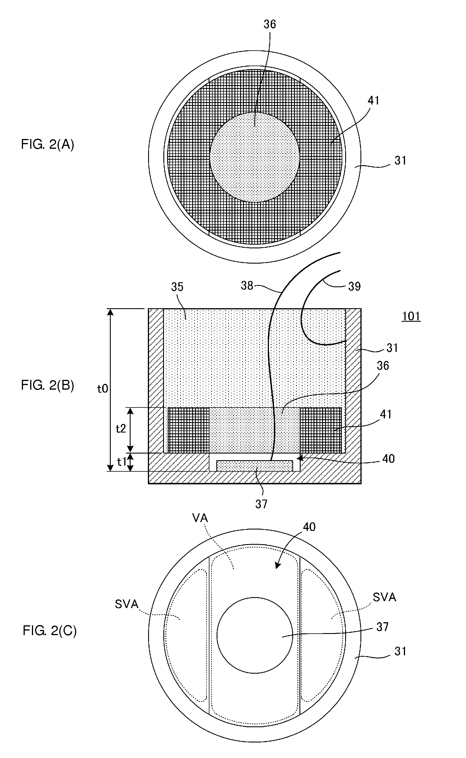
[0029]FIG. 2(A) is a plan view of an ultrasonic vibration device 101 according to a first embodiment before being filled with a filling member 35, as viewed from the side of an opening surface of a case 31. FIG. 2(B) is a cross-sectional view of the ultrasonic vibration device 101, and FIG. 2(C) is a plan view of the case 31 as viewed from the side of the opening surface thereof.
[0030]As illustrated in FIG. 2(B) and FIG. 2(C), the case 31 is a cylindrical case with a bottom. An inner bottom surface of the case 31 is formed with a substantially oblong recess 40 having a long axis and a short axis. A piezoelectric element 37 is bonded to the center of this recess 40 (also the center of the inner bottom surface of the case 31). The substantially oblong recess 40 in the inner bottom surface of the case 31 mainly forms a vibration area VA. Further, vibration suppression areas SVA thicker than the vibration area are disposed on the opposite sides of the vibration area VA in the inner bott...
second embodiment
[0064]FIG. 7(A) is a plan view of an ultrasonic vibration device 102 according to a second embodiment before being filled with a filling member 35, as viewed from the side of an opening surface of a case 31. FIG. 7(B) is a cross-sectional view of the ultrasonic vibration device 102, and FIG. 7(C) is a plan view of the case 31 as viewed from the opening surface thereof.
[0065]The structure of the case 31 is the same as the one illustrated in FIGS. 2(A) to 2(C) in the first embodiment. As illustrated in FIG. 7(C), an inner bottom surface of the case 31 is formed with a substantially oblong recess 40 having a long axis and a short axis. A piezoelectric element 37 is bonded to the center of this recess 40. The substantially oblong recess 40 in the inner bottom surface of the case 31 mainly forms a vibration area VA. Further, vibration suppression areas SVA thicker than the vibration area are disposed on the opposite sides of the vibration area VA in the inner bottom surface of the case 3...
third embodiment
[0071]FIG. 8(A), FIG. 8(B), and FIG. 8(C) are plan views of three types of reinforcing members used in an ultrasonic vibration device according to a third embodiment.
[0072]Although the ring-shaped reinforcing member 41 is provided in the first and second embodiments, it suffices if the reinforcing member has a structure reinforcing the two vibration suppression areas SVA. For example, the reinforcing member may be divided into two parts, as in reinforcing members 51 and 52 illustrated in FIG. 8(A). In this case, the reinforcing member serving as a weight on the vibration suppression areas SVA extends across the two vibration suppression areas SVA. Thereby, the reinforcing member is not displaced together with the vibration suppression areas SVA, and it is possible to enhance the effect of the reinforcing member. Further, the reinforcing member may be integrated into a disc shape, as in a reinforcing member 52 illustrated in FIG. 8(B). Further, the reinforcing member may have a shape...
PUM
 Abstract
Description
Claims
Application Information