Fiber optic current sensor

a current sensor and fiber optic technology, applied in the direction of voltage/current isolation, magnetic field magnitude/direction, measurement devices, etc., can solve the problems of sensor sensitivity, affecting the accuracy of the sensor, and difficult to achieve this property, etc., to achieve the effect of high-efficiency construction

Active Publication Date: 2012-11-15
CLOSED PROFOTECH CJSC PROFOTECH
View PDF7 Cites 20 Cited by
  • Summary
  • Abstract
  • Description
  • Claims
  • Application Information

AI Technical Summary

Benefits of technology

[0015]Benefits of the invention include increased sensitivity and precision of the fiber optic current sensor. These benefits are obtained by virtue of the reduced sensitivity of the elements of the current-sensing system to environmental conditions, such as temperature and / or mechanical stress or vibration.
[0018]Some additional benefits are achieved by embodiments in which the fiber line is a bifilar fiber line having a first port with a first arm and second arm and a second port with a first arm and a second arm; the second port of the polarization modulator is coupled to the first arm of first port of the bifilar fiber line; the first and second arms of the second port of the bifilar fiber line are respectively coupled to the first end and second end of the current-sensing fiber loop; the second arm of the first port of the bifilar fiber line is coupled to the radiation reflector. For instance, this embodiment renders the delay line and mode converter superfluous. In addition, this embodiment is capable of a highly efficient construction in which the modulator fiber segment forms a unitary fiber with the bifilar line and the current-sensing fiber loop.

Problems solved by technology

A straight spun birefringent fiber does hold a circular state of polarization over a long distance, but achieving this property is much more difficult when the fiber is bent, as is done when it is wrapped around a current carrying wire.
For a given length of magneto-sensitive fibers, an increase in the allowable number of fiber turns in the circuit, and hence the sensor sensitivity, is limited.
However, certain issues remain that affect the accuracy of the sensor.
It is well established that the ideal or nearly ideal quarter-wave plates are difficult and very expensive to produce in order to achieve accurate reading required in certain applications.
Known piezoelectric and electro-optical modulators have a residual level of parasitic modulation, which reduces the accuracy of the sensor.
An associated problem is that PM fiber is expensive.
Finally, one of the problems in known fiber-optic current sensors is the dependence of magneto-optical sensitivity of the fiber loop on the external temperature and mechanical stress on the fiber.
This dependence limits the accuracy of the sensor in the presence of these effects and requires a complex set of protective measures for sensitive circuits.

Method used


Image

  • Fiber optic current sensor
  • Fiber optic current sensor
  • Fiber optic current sensor

Examples


Embodiment Construction

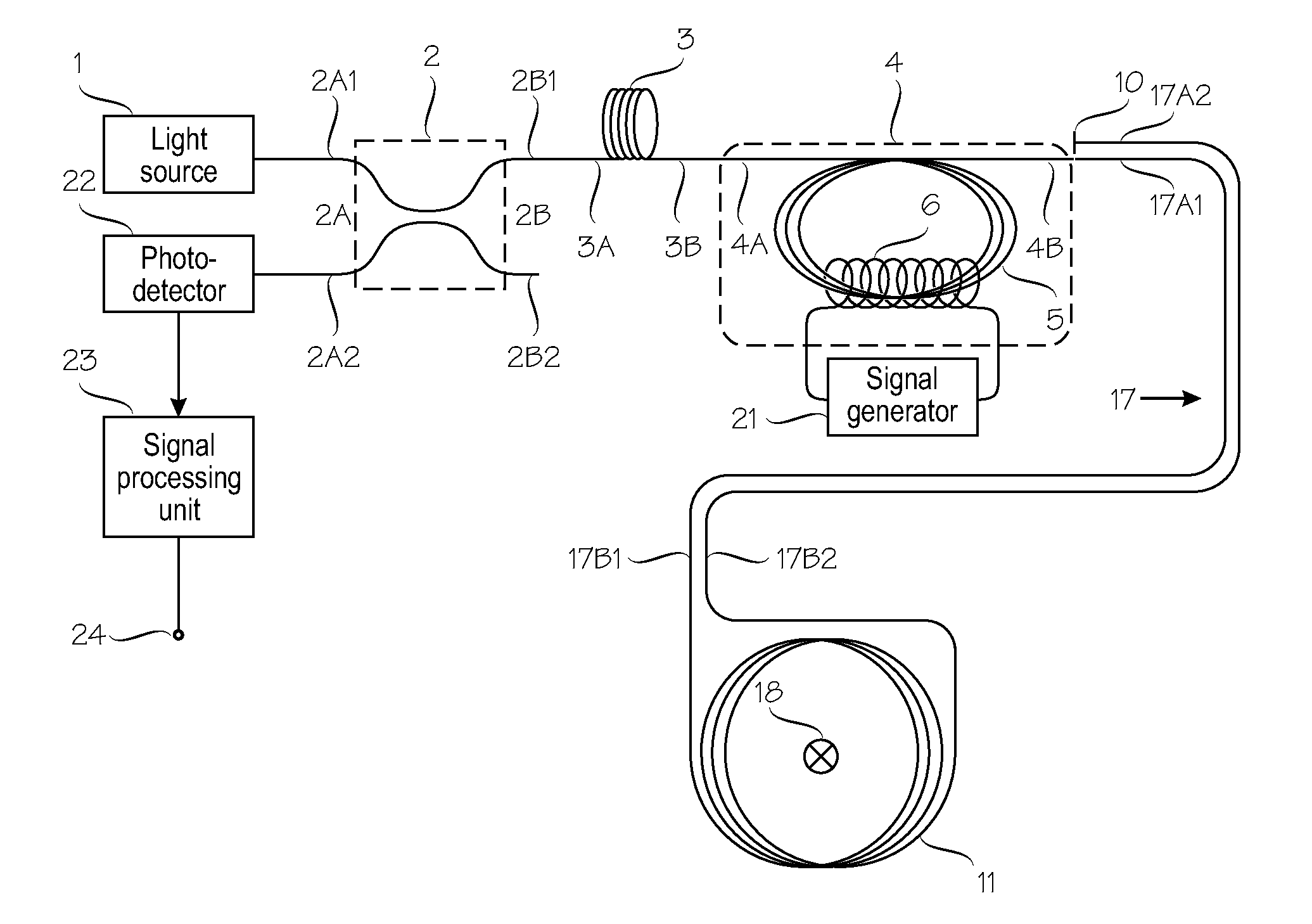
[0027]FIG. 1 shows a first embodiment of the present invention. The overall layout shown in FIG. 1 is largely similar to the layout shown in FIG. 1A of U.S. Pat. No. 6,188,811, and a detailed description of the common elements is largely superfluous. A departure from the prior art is seen in the fact that the piezoelectric birefringence modulator used in the prior art has been replaced by a magneto-optical polarization modulator 4 which comprises a modulator fiber segment 5, around which a solenoid 6 is wound. The modulator fiber segment 5 is shown as a multi-turn fiber coil, but other implementations are possible, as will be shown in more detail in the following.

[0028]Specifically, FIG. 1 shows a fiber-optic current sensor for sensing an electric current carried in an electric conductor 18. The fiber-optic current sensor comprises an optical section and an electronic section. The optical section comprises a light source 1; a directional coupler 2, a radiation polarizer 3, a polariz...


PUM


Abstract

A Fiber-optic current sensor for sensing electric current carried in an electric conductor (18). Its optical section comprises: a light source (1); a directional coupler (2) with two ports (2A, 2B) of two arms each; a radiation polarizer (3); a polarization modulator (4); a fiber line (17) coupled to a current-sensing fiber loop (11); a mirror (10); and a photodetector (22). The first port of the coupler (2) is coupled to the light source (1) and to the photodetector (22). Its second port is coupled via the radiation polarizer (3) to the polarization modulator (4). The polarization modulator comprises a magneto-sensitive element (5), around which a solenoid (6) is wound. The fiber loop (11) comprises a magneto-sensitive optical fiber with embedded linear birefringence. An electronic section comprises a signal generator (21) which drives the solenoid (6); and a signal processing unit which receives the optical signal from the photodetector (22).

Description

FIELD OF THE INVENTION[0001]The present invention relates to fiber optic current sensors and to techniques for sensing an electric current by using a fiber optic current sensor.BACKGROUND OF THE INVENTION[0002]Known fiber-optic current sensors operate on the principle of Faraday effect. The current flowing in an electric conductor (wire) induces a magnetic field, which through the Faraday effect rotates the plane of radiation polarization propagating in an optical fiber wound around the current-carrying wire. According to the theorem of magnetic field circulation, the following is obtained:Hdl=I   [1][0003]Herein I denotes the electrical current, H denotes the magnetic field and the integral is taken along a closed path around the current-carrying wire. If the sensitive fiber with constant sensitivity along the length to the magnetic field is wound around the wire, with the current as a circuit with an integral number of turns N, then the plane rotation of radiation polarization at ...

Claims


Application Information

Patent Timeline
Patent Type & Authority Applications(United States)
IPC IPC(8): G01R31/00
CPCG01R15/246G01R33/0322G01R33/032G01R15/24
Inventor CHAMOROVSKIY, YURI `GUBIN, VLADIMIRMORSHNEV, SERGEIPRZIYALKOVSKIY, YANMAXIM, RYABKOSTAROSTIN, NIKOLAYSAZONOV, ALEXANDERBOYEV, ANTON
Owner CLOSED PROFOTECH CJSC PROFOTECH
Why Eureka
Try Eureka