Substrate inspection apparatus and mask inspection apparatus

a mask inspection and substrate technology, applied in the direction of photomechanical equipment, semiconductor/solid-state device testing/measurement, instruments, etc., can solve the problem of frequent detection of false defects, and achieve the effect of improving the throughput of inspection and more accurate focus control

Active Publication Date: 2012-11-15
LASERTEC CORP
View PDF11 Cites 19 Cited by
  • Summary
  • Abstract
  • Description
  • Claims
  • Application Information

AI Technical Summary

Benefits of technology

[0022]According to the present invention, the focus control signal is produced using the focus data signal which was acquired during the scanning period in which the stage moves in the same scanning direction, so can produce a focus control signal including little error component caused by the stage movement, and thereby more accurate focus control can be carried out. Further, since the focus data signal which was acquired during the scanning of the i-th scan line is used to produce the focus co

Problems solved by technology

For instance, when the focal point of the objective lens deviates from the surface of the potomask, the captured image o

Method used


Image

  • Substrate inspection apparatus and mask inspection apparatus
  • Substrate inspection apparatus and mask inspection apparatus
  • Substrate inspection apparatus and mask inspection apparatus

Examples


Embodiment Construction

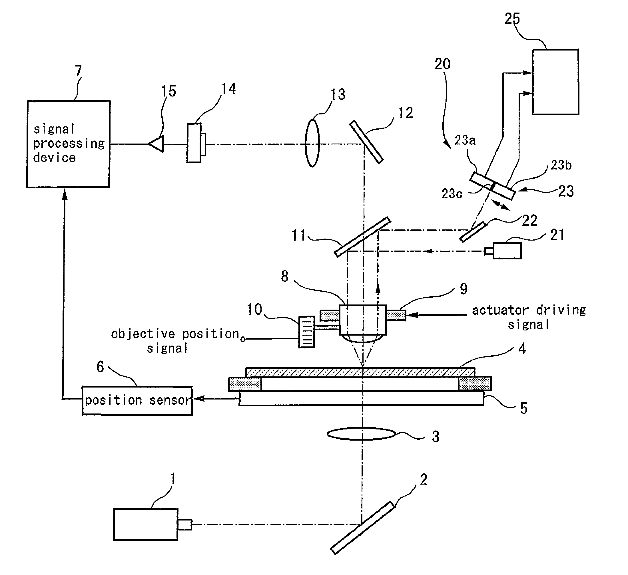
[0029]FIG. 1 is a line drawing showing one example of an optical system of the substrate inspection apparatus according to the present invention. The substrate inspection apparatus according to the invention can be used for inspection of various substrates such as a photomask, mask blanks, semiconductor substrate and glass substrate. In the present example, as the substrate to be inspected a photomask is used, and a mask inspection apparatus of a transmission type which detects a defect existing on the photomask using transmitted light will be explained. Further, the present invention can be applied to an inspection apparatus of a reflection type which detects the defects using reflected light from the photomask and an inspection apparatus which detects the defects based on a composite image consisting of a transmitted image and a reflected image of the photomask. Further, the present invention is applicable to various inspection apparatus in which image data of the substrate to be ...


PUM


Abstract

Substrate inspection apparatus, in which the acquisition of the inspection data for a defect and the acquisition of the focus data of the objective lens are performed in parallel, includes an autofocus apparatus for controlling position of the objective lens along its optical axis. The autofocus apparatus includes a focus error detection unit and a focus control signal generation unit for generating a focus control signal for controlling the position of the objective lens for each scan line using a focus data signal composed of an objective position signal or the objective position signal to which a focus error signal is added. When “i” is assumed as a positive integer and “m” is as a natural number, the focus data signal which was acquired during the scanning period of i-th scan line is used to produce the focus control signal used to scan the (i+2m)-th scan line.

Description

TECHNICAL FIELD[0001]The present invention relates to a substrate inspection apparatus and a mask inspection apparatus in which a position of an objective lens is automatically controlled.BACKGROUND ART[0002]As a mask inspection apparatus which detects a defect existing on a potomask, the mask inspection apparatus which captures a reflected image or a transmitted image of the potomask and compares the captured image with a reference image so as to detect the defects is practically used. In order to accurately detect the defect in the mask inspection apparatus, it is important to precisely control a focal point of the objective lens which focuses the reflected light or the transmitted light emitted from the potomask. For instance, when the focal point of the objective lens deviates from the surface of the potomask, the captured image of the potomask becomes blurred, and therefore the problem arises that a number of false defects are detected frequently. Furthermore, the mask patterns...

Claims


Application Information

Patent Timeline
IPC IPC(8): G01N21/88
CPCG03F1/84G03F7/7065G01N2021/95676G01N2021/95615G01N21/956H01L22/00G01N21/88
Inventor HORI, ZENTAKUSUNOSE, HARUHIKOMORIIZUMI, KOICHI
Owner LASERTEC CORP
Why Eureka
Try Eureka