Method for producing a pressure sensor assembly and pressure sensor assembly

a technology of pressure sensor and assembly, which is applied in the direction of fluid pressure measurement, manufacturing tools, instruments, etc., can solve the problems of reducing the stability thereby of the entire pressure sensor assembly, and the welding connection is additionally weakened, so as to reduce the stress of the welding connection, reduce the cost, and reduce the effect of stress

Active Publication Date: 2012-11-22
ROBERT BOSCH GMBH
View PDF6 Cites 0 Cited by
  • Summary
  • Abstract
  • Description
  • Claims
  • Application Information

AI Technical Summary

Benefits of technology

[0005]A method for producing the pressure sensor assembly in accordance with the present invention may have the advantage that the pressure sensor assembly produced is able to be used for measuring higher pressures, in particular greater than 2400 bar. According to the present invention, this is achieved by enlarging the recess of the base housing element and / or the sensor housing element by material removal, after the welding in the area of the welding connection. In this way, stresses occurring in the welding connection, in response to the application of pressure on the pressure sensor assembly, are able to be reduced. At the same time, the separation of the sensor housing element and the base housing element is maintained, which offers cost advantages in the production. In this connection, it is mentioned that the production of a single-part pressure sensor assembly would be very costly, since the pressure sensor would have to be applied onto this single-part pressure sensor assembly.
[0006]In addition, in the case of the multi-part embodiments of the sensor housing element, it is possible to use different materials for the sensor housing element and the base housing element. In this way, additional costs can be saved and the material is able to be optimized for the respective task of the component. The material of the sensor housing element, in particular, has to have great purity, while the material used for the base housing element should be extremely hard. In conventional methods for producing the pressure sensor assembly, a certain weld penetration depth absolutely has to be maintained during the production of the welding seam. That is why the weld pool backing is provided. It prevents root fusion, that is, producing a welding connection in such a way that the welding connection grasps the inner wall of the recess. The example embodiment of the present invention does away with this restriction. In addition, the geometry of the sensor housing element and / or the base housing element is able to be optimized, with respect to producing the welding seam, without restrictions, without first having to take into account the compression resistance of the finished pressure sensor assembly.
[0009]One refinement of the present invention provides that the welding take place from the outer side of the sensor housing element and the base housing element. Thus, first of all, the sensor housing element and the base housing element are positioned with respect to each other in such a way that the continuous recess is formed from the respective recesses. The recesses of the sensor housing element and the base housing element are preferably situated coaxially, in this context. Thereafter, the welding is carried out starting from the outer side of the pressure sensor assembly. A certain weld penetration depth may be set in this context, that is, the depth to which the welding connection penetrates the material of the sensor housing element and the base housing element. It is particularly preferred to produce a continuous welding connection, that is, to weld through the material of the sensor housing element and the base housing element yielding root fusion. This makes it possible to produce a very stable welding connection.
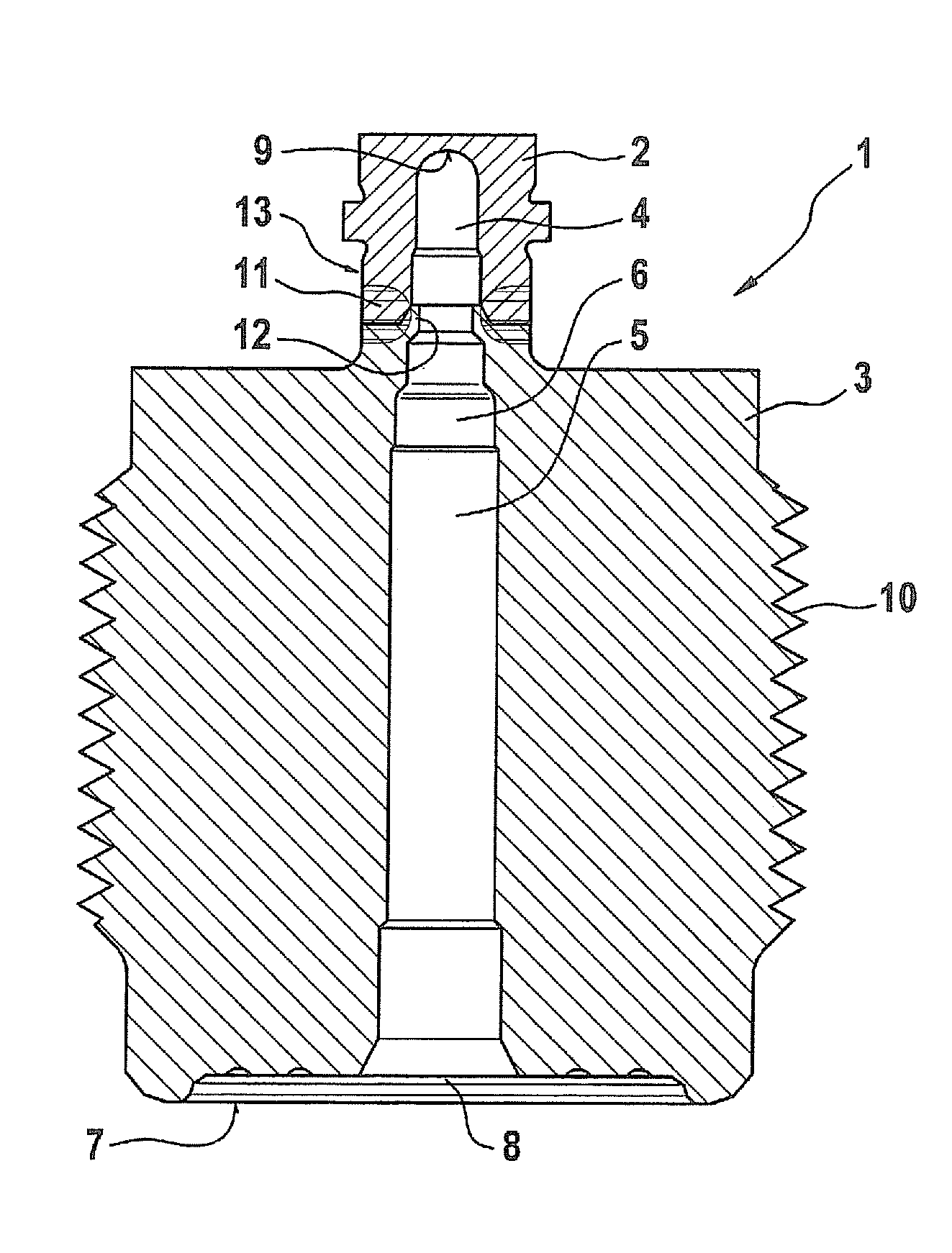
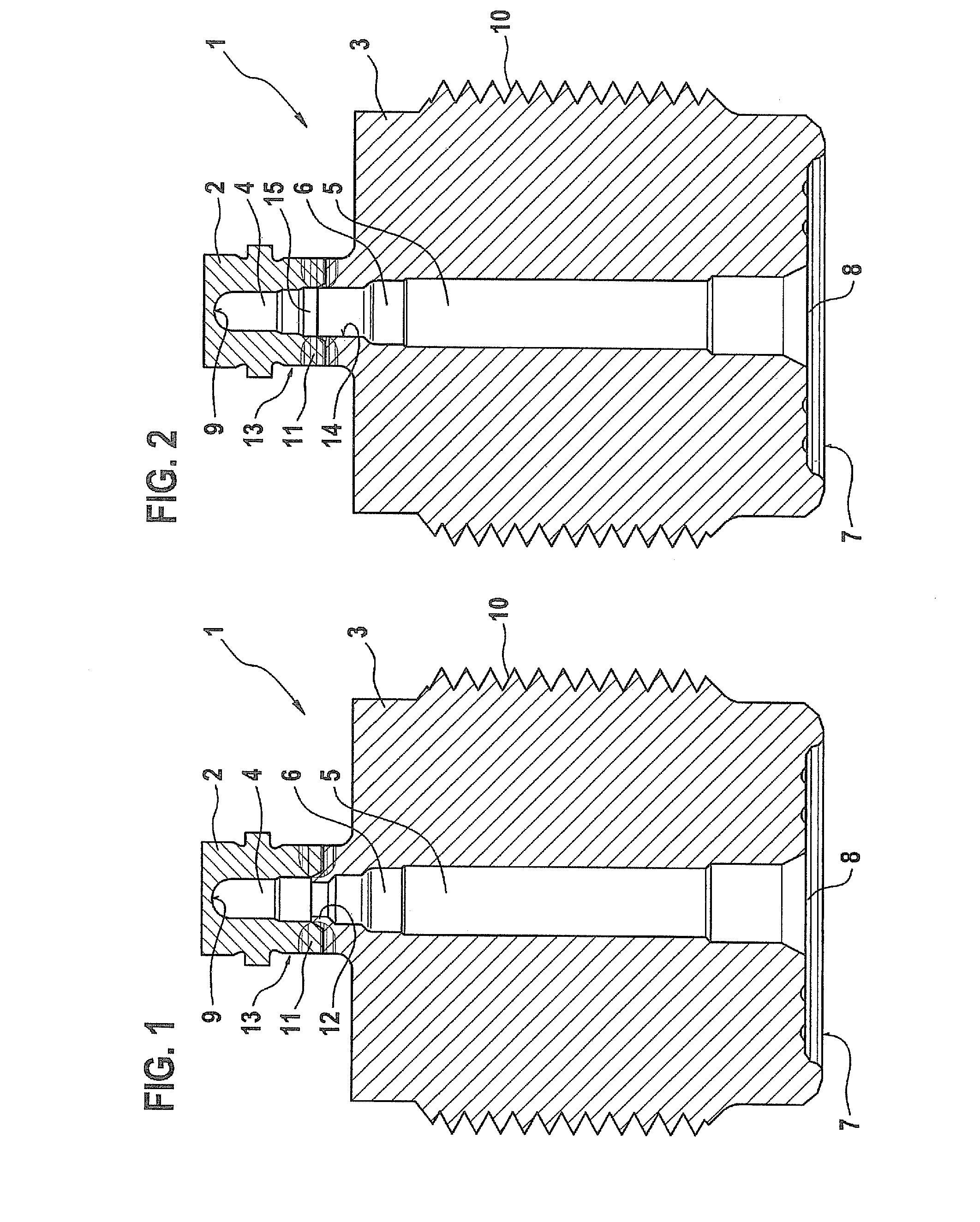
[0010]One refinement of the present invention provides that the welding connection is produced grasping an inner wall of the recess and / or grasping the weld pool backing. The former is provided particularly if the intention is to weld through the material of the sensor housing element and the base housing element. In this case, the welding connection extends in the axial direction from an outer wall of the pressure sensor assembly all the way to the inner wall of the recess. The root fusion can be provided with or without weld pool backing. If weld pool backing is provided, it may also be provided that the welding connection is not produced continuously, but only in such a way that it extends in the radial direction from the outer wall all the way to the weld pool backing. In this way, too, a reliable and safe welding connection is able to be produced. However, as described above, the weld pool backing impairs the resistance to compression of the pressure sensor assembly. This impairment is removed, however, by material removal in the area of the welding connection.
[0012]One refinement of the present invention provides that the material removal is performed by drilling, milling and / or electrochemical machining. In the drilling, the continuous recess is drilled out at least in the area of the welding connection. Using this procedure, greater quantities of material may also be simply removed. However, drilling is not suitable for every geometry and for every surface quality that is to be achieved. In contrast, if the material removal is made by milling, a greater surface quality may be attained. In addition, the geometry of the continuous recess may be designed comparatively freely. However, milling is connected with higher costs in producing the pressure sensor assembly. For this reason, it is advantageous if the geometry of the sensor housing element, the base housing element or the continuous recess is optimized in such a way that as small a quantity of material has to be removed as possible. Using electrochemical machining (ECM method), almost any desired geometry of the recess may be produced, having a very good surface quality. The costs and the processing time for electrochemical machining are a direct function of the quantity of the material to be removed, which is why the geometry should also be optimized appropriately in this case. In electrochemical machining, the geometry of the recess may be designed without compromise for the optimization of the potential gradient.

Problems solved by technology

The effect of the notch that is thus present reduces the stability of the welding connection, and thereby of the entire pressure sensor assembly.
The welding connection is additionally weakened by fusion occurring during the welding process, especially when highly tempered steels are used for the sensor housing element and / or the base housing element.
If the geometry of the sensor housing element or of the base housing element is to be optimized with respect to a higher resistance to compression of the pressure sensor assembly, this always has the effect that the welding becomes more difficult to carry out.
In sensor housing elements and base housing elements which are designed only for high resistance to compression, the welding is frequently not possible at all.
In this connection, it is mentioned that the production of a single-part pressure sensor assembly would be very costly, since the pressure sensor would have to be applied onto this single-part pressure sensor assembly.
Heat cracks occurring on the surface of the welding connection, that is, on the inner wall of the recess, particularly during root fusion, may also be enlarged by the material removal.
However, as described above, the weld pool backing impairs the resistance to compression of the pressure sensor assembly.
However, drilling is not suitable for every geometry and for every surface quality that is to be achieved.
However, milling is connected with higher costs in producing the pressure sensor assembly.
Such a development was not practicable up to now in conventional pressure sensor assemblies, because the welding connection, which grasps the inner wall of the recess, reduces the resistance to compression of the pressure sensor assembly.

Method used


Image

  • Method for producing a pressure sensor assembly and pressure sensor assembly
  • Method for producing a pressure sensor assembly and pressure sensor assembly

Examples


Embodiment Construction

[0020]FIG. 1 shows a cross section through a pressure sensor assembly 1 according to a first production step. Pressure sensor assembly 1 is made up of a sensor housing element 2 and a base housing element 3. Sensor housing element 2 has a first recess 4 and base housing element 3 has a second recess 5. Sensor housing element 2 is situated in such a way with respect to base housing element 3 that recesses 4 and 5 are situated coaxially with respect to each other, and thus form a continuous recess 6. Recess 4 is developed as a blind opening, and is thus only open in the direction of recess 5. By contrast, recess 5 reaches through base housing element 3 completely, so that continuous recess 6 ends in it on the side of sensor housing element 2, and on the side of base housing element 3 it opens out into a side surface 7 of pressure sensor assembly 1, and thus a connecting opening 8 is developed.

[0021]At the lowest point of recess 6, that is, in the region of sensor housing element 2, a ...


PUM

PropertyMeasurementUnit
pressuresaaaaaaaaaa
pressureaaaaaaaaaa
areaaaaaaaaaaa

Abstract

A method is described for producing a pressure sensor assembly, the pressure sensor assembly having a sensor housing element having a pressure sensor and a base housing element, which have a continuous recess accommodating the pressure sensor and are welded to each other. It is provided that, after the welding, in the area of the welding connection, the recess of the base housing element and / or the sensor housing element is enlarged by material removal. A pressure sensor assembly is also described.

Description

FIELD OF THE INVENTION[0001]The present invention relates to a method for producing a pressure sensor assembly, the pressure sensor assembly having a sensor housing element having a pressure sensor and a base housing element, which have a continuous recess accommodating the pressure sensor and are welded to each other. The present invention also relates to a pressure sensor assembly.BACKGROUND INFORMATION[0002]A pressure sensor assembly may be in multi-part form. In order to produce the pressure sensor assembly, the sensor housing element together with the pressure sensor and the base housing element are produced. Both the sensor housing element and the base housing element have a recess. It may be provided, in this context, that the recess of the sensor housing element is a blind recess, that is, it does not fully reach through the sensor housing element. By contrast, it is usually provided that the recess of the base housing element does fully reach through it. Thereafter, the sen...

Claims


Application Information

Patent Timeline
Patent Type & Authority Applications(United States)
IPC IPC(8): G01L7/00B23K31/02
CPCG01L9/0042G01L19/14G01L19/0046
Inventor LEDERMANN, MARKUSKAISER, RALFSTOLL, OLIVERPANHOELZL, BERNHARDROESSER, CHRISTIANRUETH, FALK
Owner ROBERT BOSCH GMBH
Why Eureka
Try Eureka