Microfluidic component for manipulating a fluid, and microfluidic chip

a microfluidic component and fluid technology, applied in fluid pressure control, laboratory glassware, instruments, etc., to achieve the effect of increasing the pressure in the control fluid and reducing the volume of the second control chamber

Inactive Publication Date: 2012-11-29
ROBERT BOSCH GMBH
View PDF6 Cites 27 Cited by
  • Summary
  • Abstract
  • Description
  • Claims
  • Application Information

AI Technical Summary

Benefits of technology

[0004]The present invention provides a microfluidic component, more particularly a micropump, a microvalve or a micromixer, for manipulating a fluid, having a first substrate, a second substrate and a third substrate, which is arranged between the first substrate and the second substrate and made of an elastic material. At least one first recess is made in the side of the first substrate which faces the third substrate, said recess forming a first control chamber. At least one second recess is made in the side of the second substrate which faces the third substrate, said recess forming a fluid channel or a fluid chamber, which is for the fluid to be manipulated and at least in portions overlaps with the first control chamber. Additionally, a second control chamber, which is spatially separated from the first control chamber, and a control channel are made in the first substrate, with the control channel connecting the first control chamber to the second control chamber. The control chambers and the control channel form a closed system and are filled with a control fluid. At least one sidewall of the second control chamber is made of elastic material and can be deformed by an actuator, more particularly a mechanical activation member of an actuator, such that the internal volume of the second control chamber is reduced and, as a result thereof, the pressure in the control fluid increases.
[0006]This spatial separation between the actuation system and the actual manipulation location of the fluid enables an improved disentanglement of the control chambers and channels, which contain the control fluid in the chip, from the fluid chambers and channels, which hold the fluid to be manipulated in the chip. As a result of this it is, in turn, possible to position the second control chambers and hence the points of contact with the actuators at predefined, standardized positions of a microfluidic chip, and this makes it possible to activate different applications, i.e. different microfluidic components, using a standard actuation system.
[0008]The actuation of the microfluidic component implemented by deforming a sidewall of the second control chamber also leads to the actuator no longer needing to be integrated directly in the chip, but instead advantageously only being loosely connectable to the microfluidic component. Microfluidic components and the chips which carry them are often embodied as disposable cartridges, particularly in the case of application in the field of biotechnology or medical engineering. This loose connectability of the actuator to the microfluidic component and the separability of the two units after activation accompanying this make it possible to design the actuation system in the form of a reusable, preferably portable, control unit. In the case of an appropriate design of the chips, particularly in the case of appropriate arrangement of the second control chambers of the microfluidic components arranged on a chip, the control unit can even be used universally for different microfluidic chips, which significantly reduces the required financial expenditure. Here, the control unit can comprise a single actuator, optionally with a plurality of activation members, or else a plurality of actuators with respectively one or more activation members.
[0012]The embodiments in which the actuator acts on a portion of the first or second substrate and not, or at least not directly, on the third substrate are particularly advantageous if relatively high restoring forces are required within the closed system filled with the control fluid.
[0013]Both gases and liquids can be used as control fluid. According to a preferred embodiment, air is used as control fluid, and so the microfluidic component is actuated pneumatically. This offers the advantage of being able to dispense with a complicated filling procedure for the control chambers and the control channel. In the case of using incompressible or almost incompressible liquids as control fluids, the volumes of the control chambers can be reduced compared to when they are filled with gases. However, on the other hand, this also results in higher flow resistances, which leads to an increase in the switching times.

Problems solved by technology

In the case of conventional actuation directly at the manipulation point there may be problems when designing the chip as a result of the actuation system, which is often relatively large.

Method used


Image

  • Microfluidic component for manipulating a fluid, and microfluidic chip
  • Microfluidic component for manipulating a fluid, and microfluidic chip
  • Microfluidic component for manipulating a fluid, and microfluidic chip

Examples


Embodiment Construction

[0022]In the figures, identical or functionally equivalent components are respectively denoted by the same reference sign.

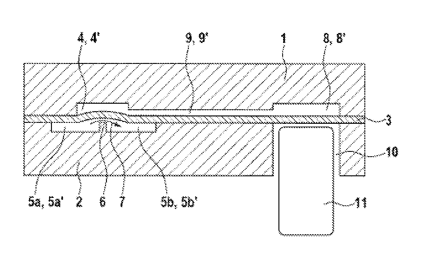
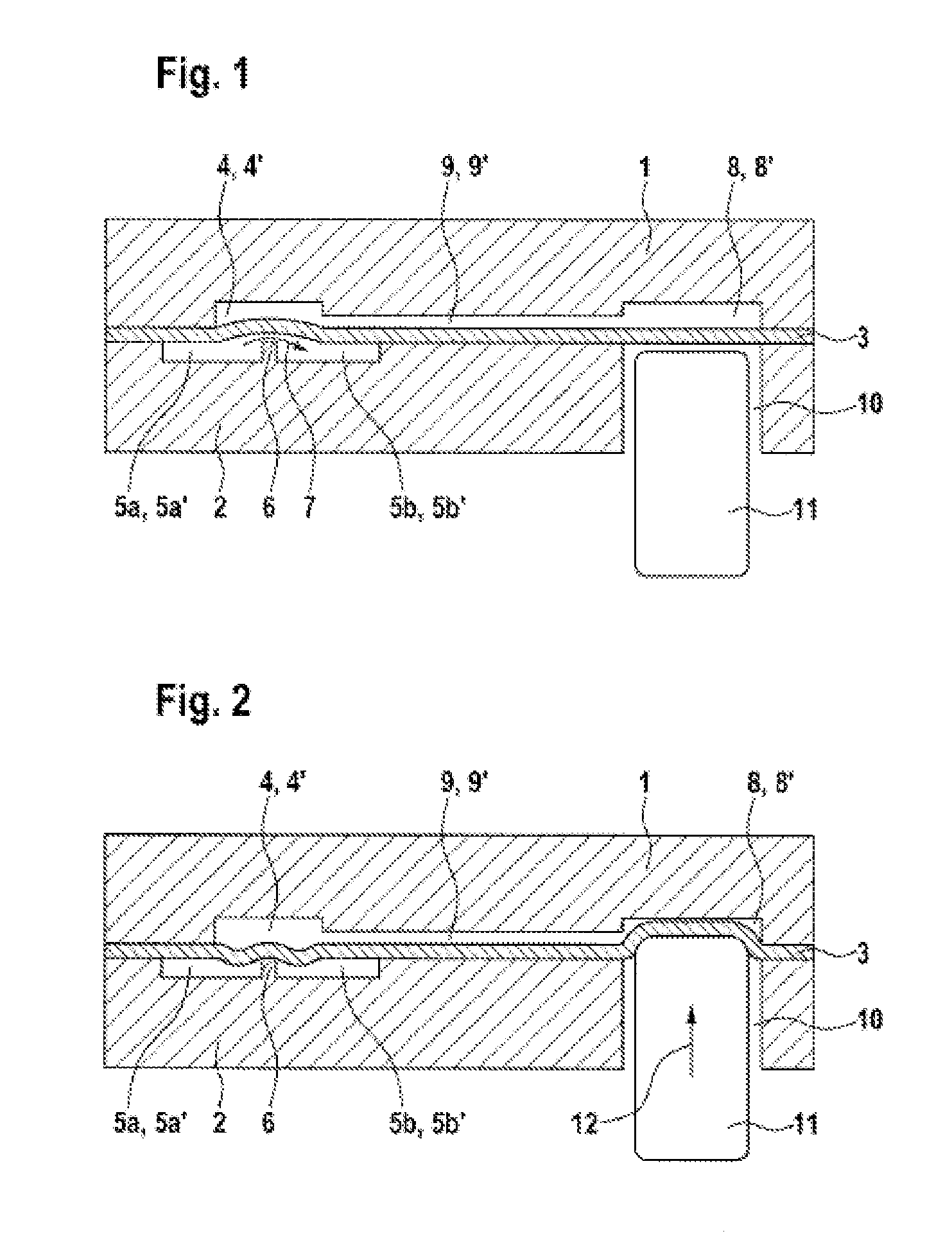
[0023]FIG. 1 shows a schematic cross section through a first embodiment of a microfluidic component according to the invention in the form of a microvalve in the non-activated state. The illustrated microvalve comprises a first substrate 1, a second substrate 2 and a third substrate 3, which is arranged between the first substrate and the second substrate. By way of example, the first and second substrate can be embodied from a thermoplastic. The third substrate 3 is made of an elastic material, more particularly a thermoplastic elastomeric film, and is arranged, more particularly sandwiched, between the first substrate 1 and the second substrate 2. Here, the first substrate 1 adjoins the third substrate 3 and, on the side adjoining the third substrate, has a first recess 4, which forms a first control chamber 4′. The second substrate 2 likewise adjoins the third...


PUM


Abstract

A microfluidic component for manipulating a fluid includes a first substrate, a second substrate, and a third substrate that is configured from a resilient material and arranged between the first substrate and the second substrate. At least one first recess that forms a first control chamber is configured on the face of the first substrate facing the third substrate. At least one second recess that forms a fluid channel is configured on the face of the second substrate facing the third substrate. A second control chamber that is spatially separated from the first control chamber and a control channel that connects the first control chamber to the second control chamber are formed in the first substrate. At least one lateral wall of the second control chamber is configured from resilient material and is deformable by an actuator such that the inner volume of the second control chamber decreases.

Description

[0001]The invention relates to a microfluidic component for manipulating a fluid and to a microfluidic chip.PRIOR ART[0002]Microfluidics deals with the manipulation of fluids, i.e. liquids or gasses, in very constrained spaces. In the process, fluids are moved, mixed, separated or processed in any other manner. Micropumps deliver or meter fluids, microvalves determine a direction or movement mode of pumped fluids and micromixers enable targeted mixing of fluid volumes. Microfluidic components are used, inter alia, in biotechnology and medical engineering.[0003]The German patent application DE 10 2008 002 336.1-12, which is a prior publication, has disclosed a microfluidic component in the form of a pinch valve, which has a first, second and third substrate, wherein the third substrate is made of an elastic material and arranged between the first and second substrate. Here, the first substrate adjoins the third substrate and has at least one first recess on the side adjoining the thi...

Claims


Application Information

Patent Timeline
Patent Type & Authority Applications(United States)
IPC IPC(8): G05D16/06
CPCB01L3/502738B01L2300/0816B01L2400/0655F16K2099/0084F16K99/0015F16K99/0061F16K2099/008F16K99/0001Y10T137/87917
Inventor ROTHACHER, PETER
Owner ROBERT BOSCH GMBH
Why Eureka
Try Eureka