
Low-thickness thermostructural composite material part, and manufacture method

a composite material, low-thickness technology, applied in the direction of machine/engine, weaving, rocket engine plant, etc., can solve the problems of large material loss, fiber destruction or bare, residual irregular porosity after densification,

Active Publication Date: 2012-11-29
SAFRAN CERAMICS SA
View PDF5 Cites 19 Cited by
  • Summary
  • Abstract
  • Description
  • Claims
  • Application Information

AI Technical Summary

Benefits of technology

[0013]An object of the invention is to provide a thermostructural composite material part which is suitable for the above-mentioned applications, while ensuring that at least a portion of the part presents a thickness that is small, and which has a fiber reinforcement that is obtained by multilayer weaving, which weaving makes use of a relatively large number of layers, including in the portion of small thickness.
[0032]The invention is remarkable in that by spreading the yarns of the multilayer fabric, it is possible to produce a fiber preform of small thickness that enables thin parts or portions of parts to be made out of composite material, i.e. having a thickness of less than 2 mm or even less than 1 mm, while preserving the presence of layers of yarns in sufficient number to obtain good mechanical properties.
[0034]Spreading the yarns of the multilayer fabric is also advantageous in that it makes it possible to reduce the macroporosity of the multilayer fabric (spacing between yarns), which is favorable for densifying the preform.
[0035]Another advantage that is obtained is a reduction in the surface relief of the multilayer fabric, thereby making it possible on the resulting part to obtain an improved surface state for an application in the field of aviation.

Problems solved by technology

When a part or a portion of a part is thin there is a problem of making a fiber preform that is suitable for obtaining the properties that are desired for the part that is to be fabricated.
The known technique that consists in forming a fiber preform by needling together superposed layers is hardly suitable since in order to obtain a fiber preform that is thin and that has uniform characteristics, it is necessary to begin by making a fiber structure of much greater thickness and then make use of its central portion only, thereby giving rise to large losses of material.
The known technique that consists in forming a fiber preform by a multilayer woven structure also presents drawbacks.
It is indeed possible to perform surface machining to improve that situation, however that leads to fibers being destroyed or laid bare, which is undesirable.
In addition, the existence of macropores makes it inevitable that there will be residual irregular porosity after densification.

Method used


Image

  • Low-thickness thermostructural composite material part, and manufacture method
  • Low-thickness thermostructural composite material part, and manufacture method
  • Low-thickness thermostructural composite material part, and manufacture method

Examples


example 1

Of the Invention

[0061]A thin plate of CMC material was made as follows.

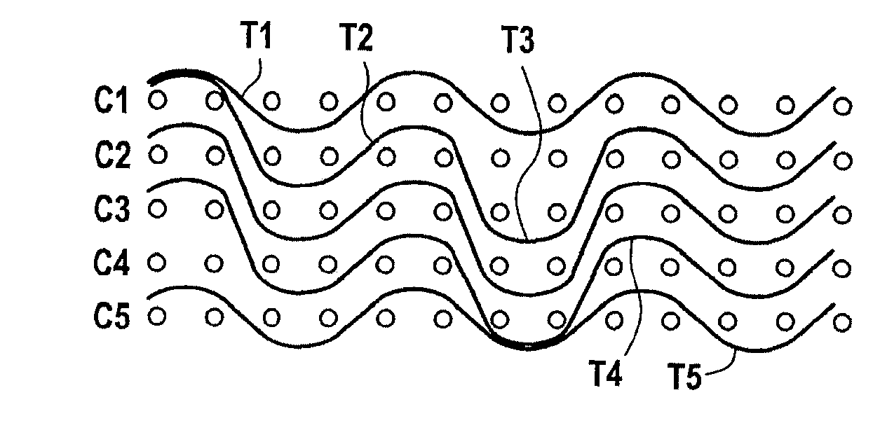
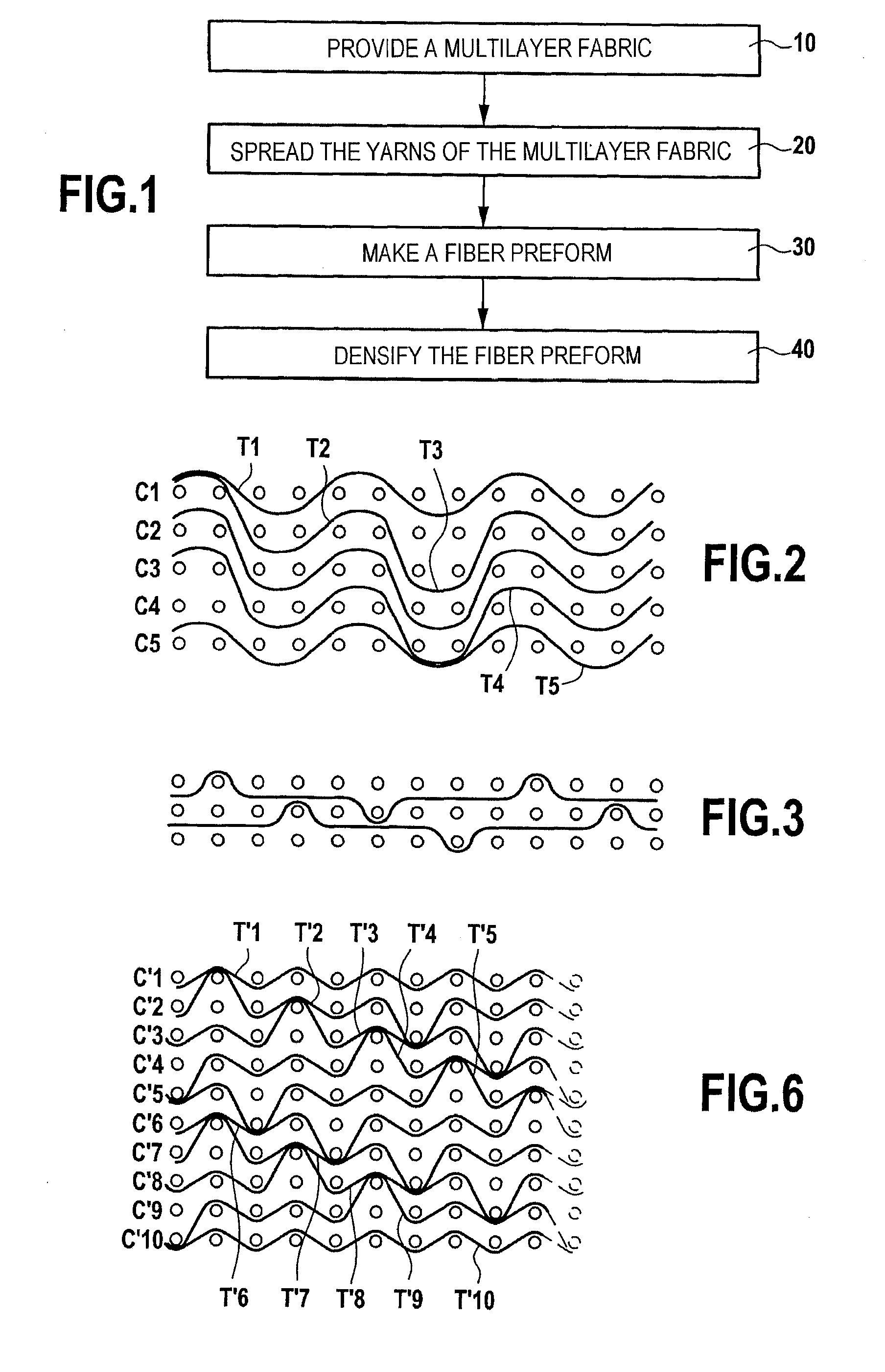
[0062]A multilayer fabric having a two-up two-down multi-serge type weave was made with SiC yarns weighing 200 tex as supplied under the name “Nicalon” by the Japanese supplier Nippon Carbon. The warp and weft thread counts were 5×5 (five warp yarns per centimeter in the weft direction in each layer of warp yarns and five weft yarns per centimeter in the warp direction in each layer of weft yarns). The number of layers was equal to five, i.e. five layers C1 to C5 of warp yarns and five layers of weft yarns T1 to T5.

[0063]FIG. 2 shows a first weft plane (the warp yarns being in section), and the other weft planes can be deduced therefrom by successive one-step shifts in the weft direction between the columns of warp yarns. The yarns T1 and T5 link the yarns of the surface warp layers C1 and C5 in a conventional serge weave (two-dimensional weaving). The yarn T2 links together warp yarns of the layers C1, C2, C3, w...

example 2

Of the Invention

[0072]A multilayer fabric having a multi-plain type weave was made using the same yarns as in Example 1. The thread count in the warp and weft directions was 2.5×2.5. The number of layers was ten, i.e. ten layers C′1 to C′10 of warp yarns and ten layers of weft yarns T′1 to T′10.

[0073]FIG. 6 shows a first weft plane, the other weft planes being deduced therefrom by successive shifts in the weft direction. The yarns T′1 and T′10 link the yarns of the surface warp layers C′1 and C′10 in a conventional plain weave. The other weft yarns T′2 to T′9 link together warp yarns in sets of three adjacent layers, e.g. the yarn T′2 links together the warp yarns in layers C′1, C′2, and C′3.

[0074]This produced a multilayer fabric having thickness equal to about 1.6 mm under a load of 5 kPa.

[0075]The yarns of the fabric were spread by subjecting the fabric to vibration until its thickness was reduced to a value equal to about 1.37 mm under a load of 5 kPa. The fiber volume ratio was...


PUM

PropertyMeasurementUnit
thicknessaaaaaaaaaa
thicknessaaaaaaaaaa
thicknessaaaaaaaaaa

Abstract

A thermostructural composite material part including carbon or ceramic fiber reinforcement densified by a matrix having at least one thin portion in which: the thickness of the part is less than 2 mm, or indeed less than 1 mm; the fiber reinforcement is made as a single thickness of multilayer fabric made of spread yarns having a weight of not less than 200 tex; the fiber volume ratio lies in the range 25% to 45%; and the ratio between the number of layers of the multilayer fabric and the thickness in millimeters of the part is not less than four.

Description

BACKGROUND OF THE INVENTION[0001]The invention relates to thermostructural composite material parts, and more precisely to such parts in which there is at least a portion that is of small thickness, i.e. of thickness less than 2 millimeters (mm).[0002]The invention applies more particularly to structural parts for aviation and space applications, in particular afterbody parts for gas turbine aeroengines, nozzle exhaust cones, . . . .[0003]For such parts, proposals have been made to use thermostructural composite materials, i.e. composite materials having mechanical properties that make them suitable for constituting structural elements and that have the ability to conserve those properties at high temperatures. Such thermostructural materials are constituted in particular by carbon / carbon (C / C) composite materials (carbon fiber reinforcement and carbon matrix), and by ceramic matrix composite (CMC) materials, e.g. C / SiC materials (carbon fiber reinforcement with a silicon carbide ma...

Claims


Application Information

Patent Timeline
Patent Type & Authority Applications(United States)
IPC IPC(8): C04B35/80D03D1/00B32B5/26
CPCC04B35/52Y10T428/2495C04B35/62868C04B35/62873C04B35/62884C04B35/62897C04B35/806C04B2235/483C04B2235/5244C04B2235/5256C04B2235/5268C04B2235/614C04B2235/616C04B2235/95D06C29/00F02K1/82F02K9/97F05D2300/603C04B35/565C04B2235/5248D03D25/005C04B35/80C04B2235/5216F05D2220/80F05D2240/128F05D2300/6012F05D2300/6033
Inventor CHARLEUX, FRANCOISCOUPE, DOMINIQUEPHILIPPE, ERIC
Owner SAFRAN CERAMICS SA
Learn More