Oven-controlled crystal oscillator

Active Publication Date: 2012-12-06
NIHON DEMPA KOGYO CO LTD
View PDF3 Cites 7 Cited by
  • Summary
  • Abstract
  • Description
  • Claims
  • Application Information

AI Technical Summary

Benefits of technology

[0016]With the above configuration, a thermistor which generally have highly non-linear, negative resistance-temperature characteristics detects the temperature in the thermostatic oven and feeds back the detected temperature to the inverting input terminal (i.e., (−) input) of the differential amplifier. A so-called resistor network made up of first and second resistors and connected to the non-inverting input terminal (i.e., (+) input) of the differential amplifier

Problems solved by technology

However, even if such adjustments are made, depending on the structure of the thermostatic oven and arrangement of the thermistor in the thermostatic oven, the thermistor temperature will not accurately match the temperature of the crystal unit.
Since control is performed based on the temperature detected by the thermistor in the thermostatic oven, if the apparent ZTC point varies, the control cannot be per

Method used


Image

  • Oven-controlled crystal oscillator
  • Oven-controlled crystal oscillator
  • Oven-controlled crystal oscillator

Examples


Embodiment Construction

[0023]Next, oven-controlled crystal oscillators according to preferred embodiments of the present invention will be described.

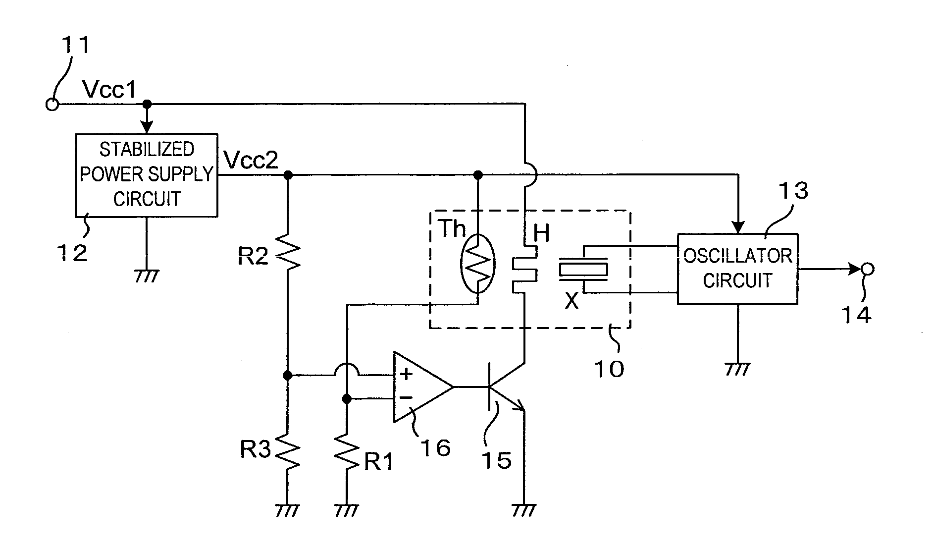
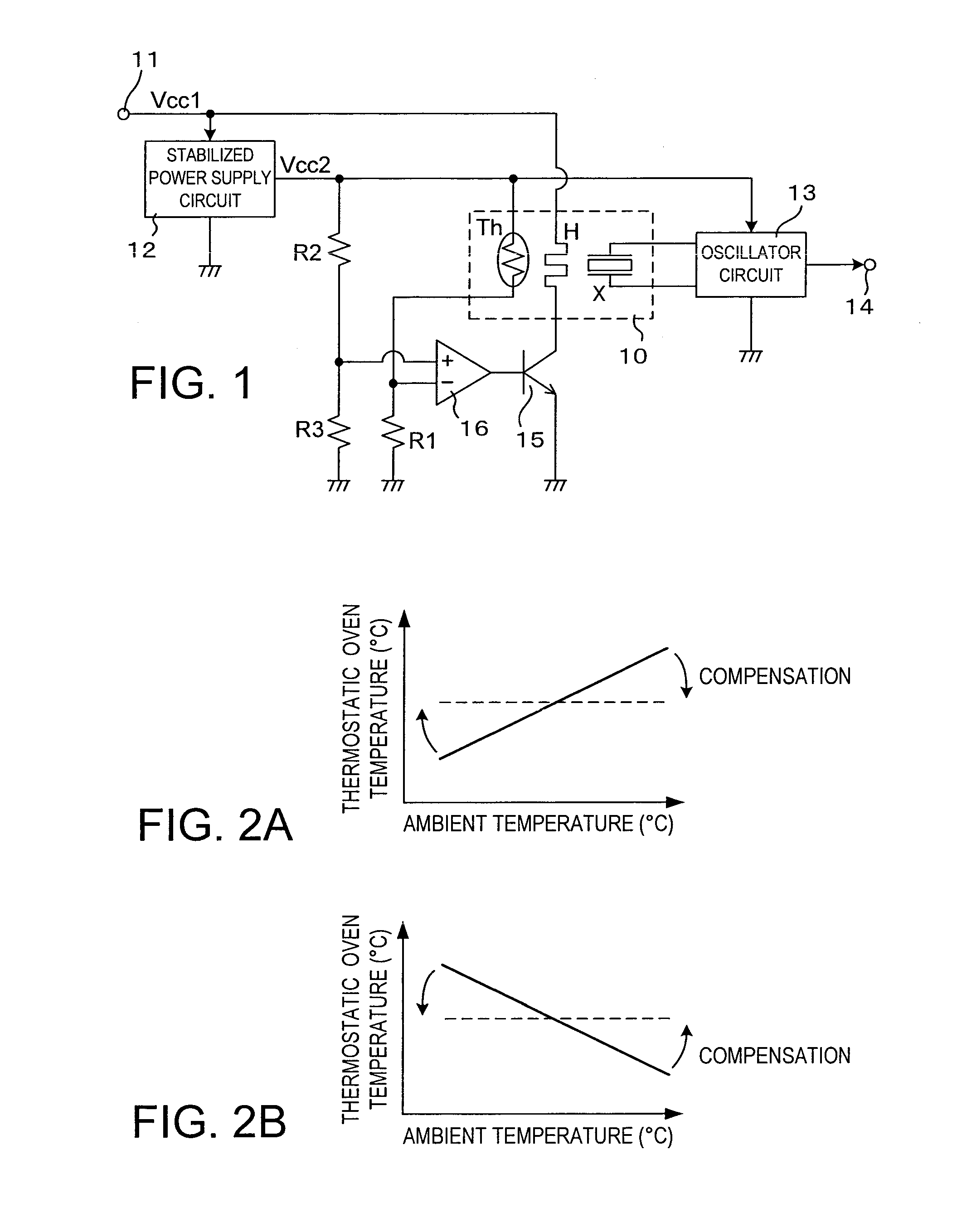
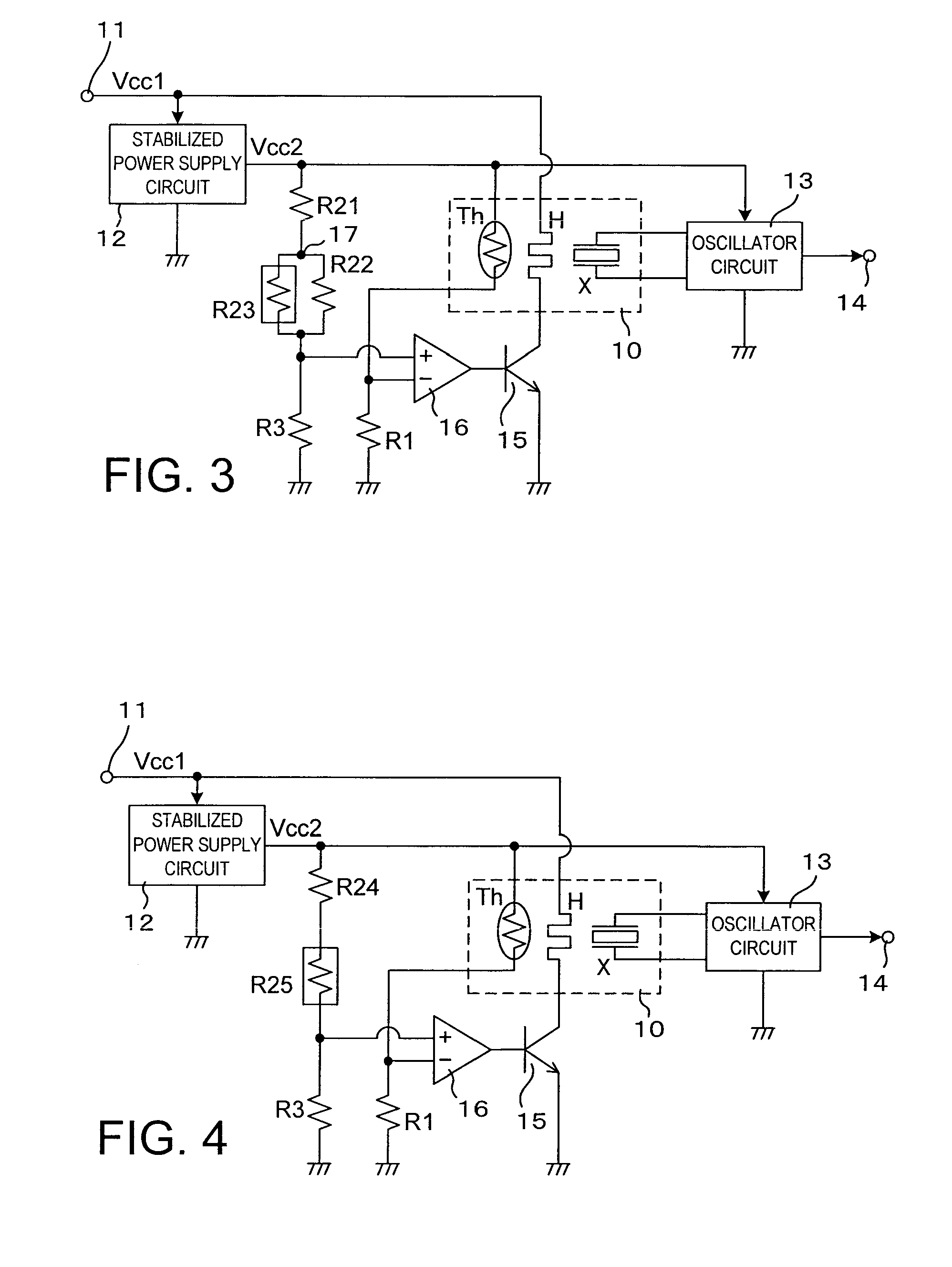
[0024]An oven-controlled crystal oscillator according to an embodiment of the present invention shown in FIG. 3 is similar to the one shown in FIG. 1, but differs from the one shown in FIG. 1 in circuit configuration of the temperature control circuit. Specifically, the circuit shown in FIG. 3 has resistors R21 to R23 installed instead of resistor R2 of the circuit shown in FIG. 1. Resistor R21 is supplied at one end with power supply voltage Vcc2 and connected at the other end to connection node 17. Resistors R22 and R23 are installed in parallel between connection node 17 and the non-inverting input terminal (+) of differential amplifier 16. The circuit shown in FIG. 3 is intended to keep temperature in a thermostatic oven or a constant temperature bath constant and equal to a ZTC point of crystal unit X regardless of ambient temperature when there is a rel...


PUM


Abstract

A crystal unit and a thermistor with negative resistance-temperature characteristics are housed in a thermostatic oven heated by a heater. A transistor driving the heater is controlled by an output of a differential amplifier, the thermistor is placed between a power supply voltage and an inverting input of the amplifier, and a first resistor used to adjust the temperature of a zero temperature coefficient point of the crystal unit is installed between the inverting input and a ground point. A second resistor is installed between the power supply voltage and a non-inverting input of the amplifier and a third resistor is installed between the non-inverting input and ground point. One of the second and third resistors is a resistor assembly made up of a plurality of resistance elements and one of these resistance elements is provided with positive resistance-temperature characteristics and adapted to detect ambient temperature.

Description

BACKGROUND OF THE INVENTION[0001]1. Field of the Invention The present invention relates to an oven-controlled crystal oscillator (OCXO), the oven-controlled crystal oscillator being equipped with: a crystal unit or crystal element; a thermostatic oven which contains the crystal unit and keeps temperature of the crystal unit constant, and an oscillator circuit which uses the crystal unit.[0002]2. Description of the Related Art[0003]A crystal oscillator which incorporates, as an integral component, a quartz crystal unit and an oscillator circuit using the crystal unit outputs an oscillating signal of an accurate predetermined frequency simply when mounted on a circuit board or the like and supplied externally with a power supply voltage. The crystal oscillator is thus used widely as a frequency or time reference source in various electronic devices.[0004]A vibration frequency of the crystal unit has high stability, but changes slightly with temperature due to frequency-temperature ch...

Claims


Application Information

Patent Timeline
IPC IPC(8): H03B1/00
CPCH03L1/04
Inventor ITO, MANABUMITOME, HIROYUKI
Owner NIHON DEMPA KOGYO CO LTD
Why Eureka
Try Eureka