Body Scanner With Improved X-ray Transmission Imaging

a scanner and body technology, applied in the field of radiation energy imaging, can solve the problems of time-consuming and labor-intensive search of individuals by hand, ineffectiveness, and complex human body shape, and achieve the effects of reducing the physical size of the apparatus, eliminating blind spots, and improving digital images of the person

Active Publication Date: 2012-12-06
TEK84 INC
View PDF4 Cites 12 Cited by
  • Summary
  • Abstract
  • Description
  • Claims
  • Application Information

AI Technical Summary

Benefits of technology

[0012]The present Invention overcomes these limitations of the prior art by providing an apparatus and method capable of acquiring improved digital images of the person being screened. In one embodiment this is achieved by viewing the person with radiant energy from three directions: from the person's anterior side (i.e., the front), from the person's posterior side (i.e., the rear), and from beneath the person's feet in the standing position. Further, the present Invention views the person with two modalities of radiant energy modulation: backscatter and transmission. These tri-view and dual-mode features of the present invention, operating separately or preferably in combination, eliminate the critical blind areas of prior art systems. In one preferred embodiment the present Invention acquires six distinct and complete x-ray images of the person being examined: front-backscatter, rear-backscatter, feet-backscatter, front-transmission, rear-transmission, and feet-transmission. Further, the present Invention achieves this improvement while reducing the physical size of the apparatus compared with the prior art.
[0013]It is therefore the goal of the present Invention to provide an improved method and apparatus for detecting security threats concealed under the clothing of a person entering a security controlled area. Another goal of the invention is to provide additional images of the person being examined to eliminate blind spots where security threats may be concealed. Yet another goal is to provide complete images of the entire body, thereby further eliminating blind spots. Still another goal is to more throughly inspect the shoes worn by the person. A further goal is to provide a physically compact apparatus that occupies less floor space in the security checkpoint. Yet another goal is to obtain anterior and posterior images in rapid succession, with complete a complete field of view on both the backscatter and transmission images. Still another goal is to provide a body scanner with stationary detectors, while not requiring the person to turn their body during the examination.

Problems solved by technology

Searching individuals by hand is time consuming, often ineffective, and objectionable to both the person being screened and the security officer performing the screening.
However, the human body is complex in shape, and the type of clothing worn by people is diverse and unpredictable.
This results in areas of the body where prior art body scanners are ineffective in detecting objects.
Of particular concern are the sides of the body and the shoes, where certain types of threats are likely to be missed by prior art systems.
Further, prior art body scanners are physically large, and therefore difficult to incorporate into space-limited security checkpoints, such as airports.
Second, the x-ray may interact with the body tissue through Compton scattering, which alters its direction of propagation.
X-rays that are scattered in the forward direction, that is, into the body, are not useful and are ignored.
A limitation of the prior art embodiment of FIG. 1 is that the examined person 12 must turn their body to obtain a rear scan.
Another limitation of this embodiment is that the shoes are examined with the same apparatus that scans the whole body.
However, these images of the prior art are not sufficient to detect security threats in the shoes for two important reasons.
First, the backscatter image 50 is only a view from an angle generally above and in front of the shoes, and cannot visualize concealed objects hidden underneath the foot, or concealed within the sole and heal of the shoes.
Second, the spatial resolution of the transmission x-ray image 70 is too low to adequately inspect the shoes.
In turn, the insufficiently resolved bones in the feet produce an image clutter that drastically interferes with the visualization of concealed objects.
If the operator cannot clearly identify the complex pattern of bones in the feet, they cannot distinguish these bones from hidden objects.
However, this prior art system does not fully meet this classification, since transmission images from both the front and rear cannot be obtained of the lower legs and feet.
However, no detector is present that is capable of detecting x-rays that are transmitted through the lower legs and feet.
As thus described, prior art body scanners are limited in their ability to search persons entering security controlled areas by the number of images they can acquire of each person.
This results in blind areas in detection on the body of the person being screened.
Further, the prior art apparatus has a physically large footprint, and therefore is not able to be installed in security checkpoints where floor space is limited.
However, no prior art body scanner can do both in a single apparatus.

Method used


Image

  • Body Scanner With Improved X-ray Transmission Imaging
  • Body Scanner With Improved X-ray Transmission Imaging
  • Body Scanner With Improved X-ray Transmission Imaging

Examples


Embodiment Construction

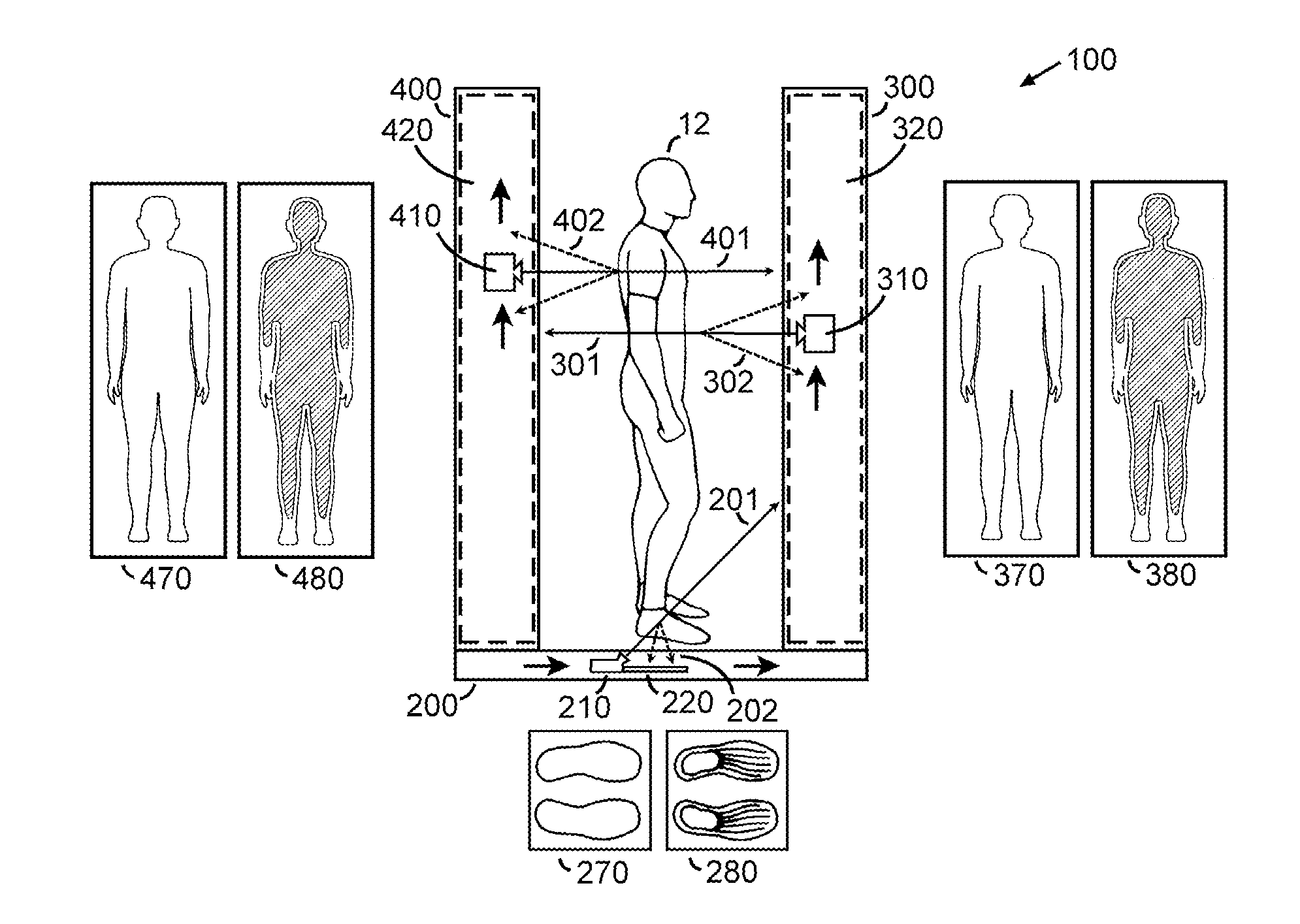
[0026]FIG. 3 depicts the overall physical structure of a preferred embodiment of the present Invention. The body scanner 100 generally comprises a base assembly 200 measuring approximately 60″ by 60″ by 4″; a front assembly 300 measuring approximately 13″ by 60″ by 96″ inches; and a rear assembly 400 measuring approximately 13″ by 60″ by 96″. The examined person 12 stands on the base assembly 200 centered between the front assembly 300 and the rear assembly 400. The front assembly 300 is joined with the base assembly 200 by front connection 309. Likewise, the rear assembly 400 is joined with the base assembly 200 by rear connection 409. The front and rear connections 309409 are preferably removable fasteners that can be connected or disconnected at will, such as bolts, clamps and tie downs known in the art. This facilitates movement of the body scanner 100 from one location to another by disassembly into three easily transported assemblies 200300400.

[0027]FIG. 4A and FIG. 4B are a m...


PUM

PropertyMeasurementUnit
widthaaaaaaaaaa
widthaaaaaaaaaa
widthaaaaaaaaaa

Abstract

The inventive body scanner is used to screen persons entering a security controlled area for the presence of security threats hidden under the clothing, such as guns, knifes, explosives and contraband. The Invention is an improvement on prior art body scanners that operate primarily by acquiring backscatter x-ray images, but only acquire transmission images over a limited part of the person's body. These prior art systems provide x-ray sources on the anterior and posterior sides of the person being screened, and x-ray sensitive detectors on the sides of these x-ray sources. While sufficient for backscatter imaging, the gaps between these detectors results in blind areas in the transmission images, resulting in lower ability to detect security threats hidden under the clothing. The present Invention overcomes these limitations of the prior art by providing x-ray sensitive detector on the outside of the x-ray sources. That is, the pair of x-ray sources are located within the pair of x-ray detectors, and the person being screened is located within the pair of x-ray sources. In conjunction with this imaging geometry, spatial offsets in the location of the x-ray sources provide effectively full transmission coverage for transmission imaging.

Description

BACKGROUND OF THE INVENTION[0001]This invention relates to the radiant energy imaging of humans to detect weapons, explosives, contraband, and other security threats hidden under the clothing.[0002]Criminals and terrorists frequently conceal security threats under their clothing, such as handguns, knifes, explosives and illicit drugs. These security threats must be detected on persons entering security controlled areas, such as prisons, airports, government buildings, nuclear power plants, military bases, and the like. Searching individuals by hand is time consuming, often ineffective, and objectionable to both the person being screened and the security officer performing the screening. Electronic imaging systems became commercially available in the 1990s to facilitate this screening process. These include the model SECURE 1000, sold by Rapiscan Security Products; model SmartCheck, sold by American Science and Engineering; and model ProVision, sold by L3 Communications. These electr...

Claims


Application Information

Patent Timeline
Patent Type & Authority Applications(United States)
IPC IPC(8): G01N23/04G01N23/201
CPCG01V5/0025G01V5/0016
Inventor SMITH, STEVEN WINN
Owner TEK84 INC
Why Eureka
Try Eureka