Process and apparatus for heating feedwater in a heat recovery steam generator

a heat recovery and feedwater technology, applied in the field of boilers, can solve the problems of sulfuric acid condense on the surface of sulfuric acid, corrode the low temperature surfaces of boilers, and increase the cost of production

Inactive Publication Date: 2012-12-13
NOOTER ERIKSEN INC
View PDF4 Cites 44 Cited by
  • Summary
  • Abstract
  • Description
  • Claims
  • Application Information

AI Technical Summary

Problems solved by technology

But this increased efficiency has created its own problems that if left unaddressed can result in corrosion of the low temperature surfaces of the boilers.
Those compounds will combine with water to produce sulfuric acid which is highly corrosive.
But if any surface drops to a temperature below the acid dew point temperature, sulfuric acid will condense on that surface and corrode it, and the vulnerable surfaces exist on the feedwater heater.
The bypass water, when employed, does not achieve the benefit of an initial temperature rise in the feedwater heater and decreases the efficiency of the HRSG.
That too decreases efficiency.
Moreover, the temperature of the exhaust gas as it passes into the feedwater heater is often not much greater than the temperature of the water leaving the feedwater heater, and as a consequence the feedwater heater must contain a rather large and expensive grouping of coils.
The large feedwater heater coupled with the bypass results in a significant pressure drop across them, and this imposes a substantial load on the feedwater pump.
However, when dew point temperature is higher, such as at 230° F. for exhaust gas derived from some fuel oils, a large temperature differential is not available at the feedwater heater (it becomes very tight—FIG. 1A).
As a consequence, the feedwater heater requires a large bundle of coils, making a conventional feedwater heater expensive in its own right and also requiring a significant head from the condensate pump just to force water through it and into the economizers and low pressure evaporator beyond it.

Method used


Image

  • Process and apparatus for heating feedwater in a heat recovery steam generator
  • Process and apparatus for heating feedwater in a heat recovery steam generator
  • Process and apparatus for heating feedwater in a heat recovery steam generator

Examples


Embodiment Construction

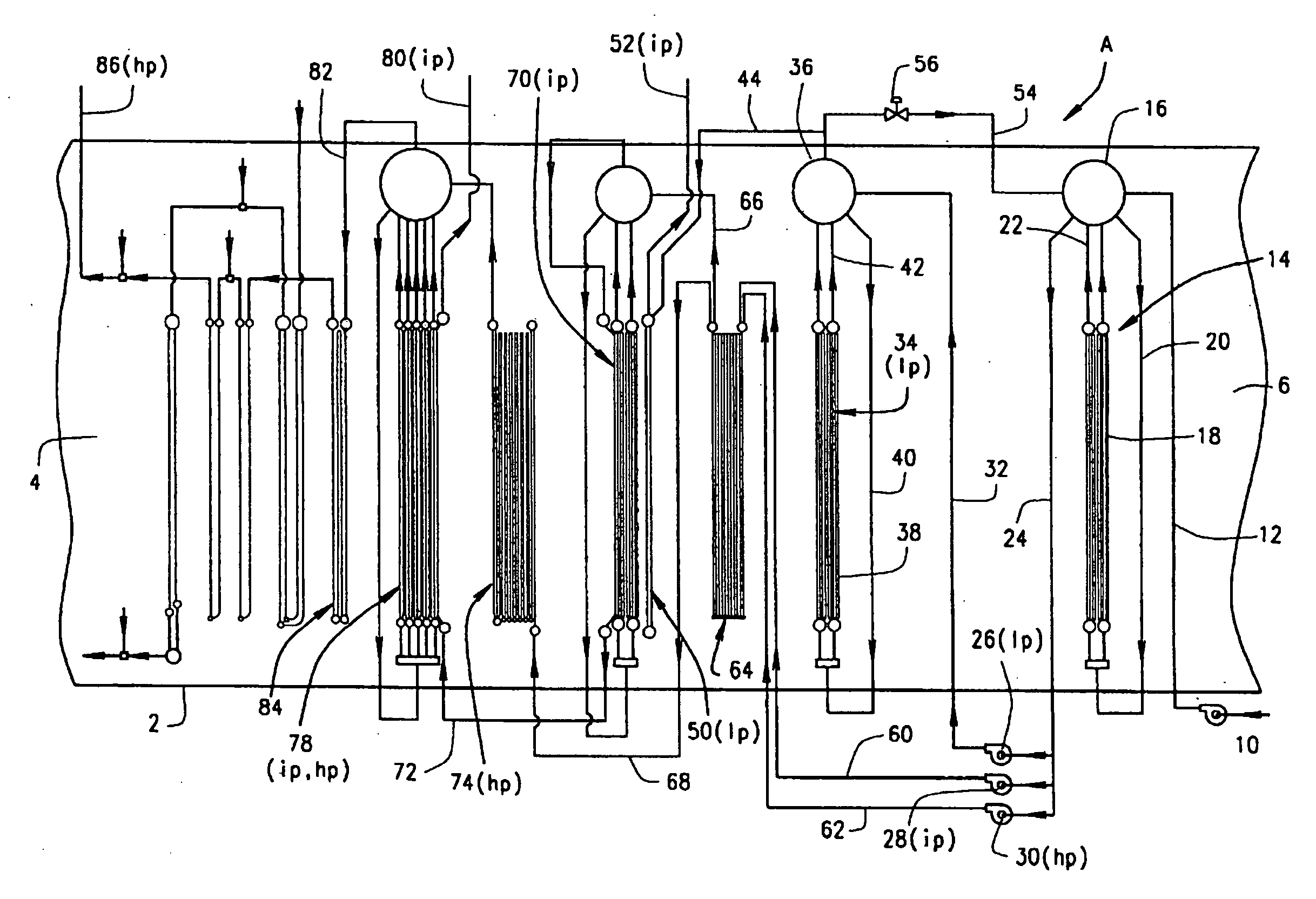
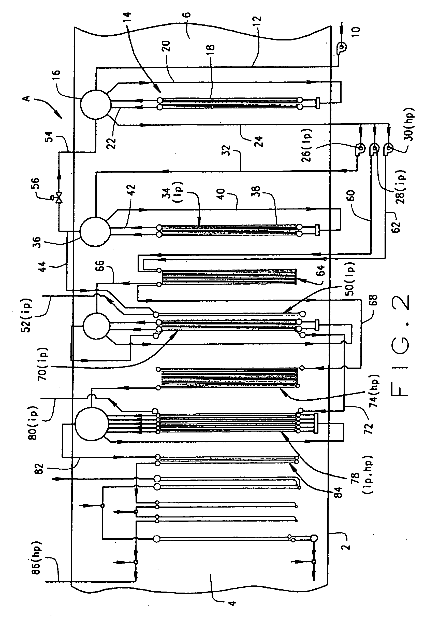
[0016]Referring now to the drawings, a heat recovery steam generator (HRSG) A (FIG. 2) that extracts heat from a hot gas flow provides superheated steam at several pressure levels. That steam may be directed to a steam turbine to power it. After passing through the turbine the steam discharges at a lower pressure and temperature and is condensed into subcooled liquid water which is circulated back to the HRSG A to again be converted into superheated steam.

[0017]The HRSG A includes (FIG. 2) a housing 2 that is basically a duct having an inlet 4 and an outlet 6. The HRSG A also includes a series of heat exchangers contained within the housing 2, and their functions are to a large measure described by their names. In addition, the HRSG A includes pumps, valves, and lines or conduits connecting the heat exchangers, pumps and valves together into the functioning HRSG A. Hot exhaust gas derived from the combustion of a fossil fuel enters the housing 2 at its inlet 4, passes through the se...


PUM


Abstract

A feedwater heater (14) in a heat recovery steam generator (A,B) lies within a flow of hot exhaust gas. The feedwater heater (14) converts subcooled feedwater into saturated feedwater water, the temperature of which is only lightly above the acid dew point temperature of the exhaust gas so that corrosive acids do not condense on coils (18) of the feedwater heater (14). Yet the temperature of the saturated feedwater lies significantly below the temperature of the exhaust gas at the coils (18), so that the coils (18) operate efficiently and require minimal surface area. Pumps (26, 28, 30) elevate the pressure of the saturated feedwater and direct it into an economizer (64, 90) where, owing to the increase in pressure, the water is again subcooled. The economizer (64, 90) elevates the temperature still further and delivers the higher pressure feedwater to evaporators (34, 70, 78) that convert it into saturated steam that flows on to the superheaters (50, 78, 84). Higher pressure pegging stem admitted to the feedwater heater (14) controls the pressure—and temperature—of saturated steam and water in the feedwater heater (14).

Description

RELATED APPLICATION[0001]This application derives priority from and otherwise claims the benefit of U.S. provisional application 61 / 300,222 filed 1 Feb. 2010, which application is incorporated herein by reference.TECHNICAL FIELD[0002]The invention relates to boilers and more particularly to a heat recovery steam generators having improved feedwater heating.BACKGROUND ART[0003]Boilers designed to convert liquid water into steam by extracting energy from hot gases have become more efficient over the years, and much of this efficiency derives from extracting heat from the gases at lower temperatures—temperatures at which the gases might otherwise be exhausted to the atmosphere. But this increased efficiency has created its own problems that if left unaddressed can result in corrosion of the low temperature surfaces of the boilers.[0004]Heat recovery steam generators (HRSGs) represent an important class of high efficiency boilers. The typical HRSG operates in a system that includes a ga...

Claims


Application Information

Patent Timeline
Patent Type & Authority Applications(United States)
IPC IPC(8): F01K13/00F01K1/00
CPCF22B1/1815F22D1/02F22B37/025F22B35/007
Inventor RECHTMAN, YURI M.
Owner NOOTER ERIKSEN INC
Why Eureka
Try Eureka