Device and system for the intermediate storage of thermal energy

a technology of thermal energy storage and intermediate storage, which is applied in the direction of storage heaters, space heating and ventilation details, domestic heating details, etc., can solve the problems of affecting the economic benefits of such a heat accumulator, requiring a relative long time interval,

Inactive Publication Date: 2012-12-13
DEUTES ZENT FUER LUFT & RAUMFAHRT A V
View PDF5 Cites 14 Cited by
  • Summary
  • Abstract
  • Description
  • Claims
  • Application Information

AI Technical Summary

Benefits of technology

[0012]It is therefore an object of the present invention to improve p

Problems solved by technology

In a solid storage medium made of concrete, this has the result that areas, directly surrounding the individual pipes, of the solid storage medium are charged very rapidly thermally, however, with increasing distance from the individual pipes a great temperature drop is to be observed (FIG. 12a), and therefore a relatively long time interval is necessary until a very largely equalized ene

Method used


Image

  • Device and system for the intermediate storage of thermal energy
  • Device and system for the intermediate storage of thermal energy
  • Device and system for the intermediate storage of thermal energy

Examples


first embodiment

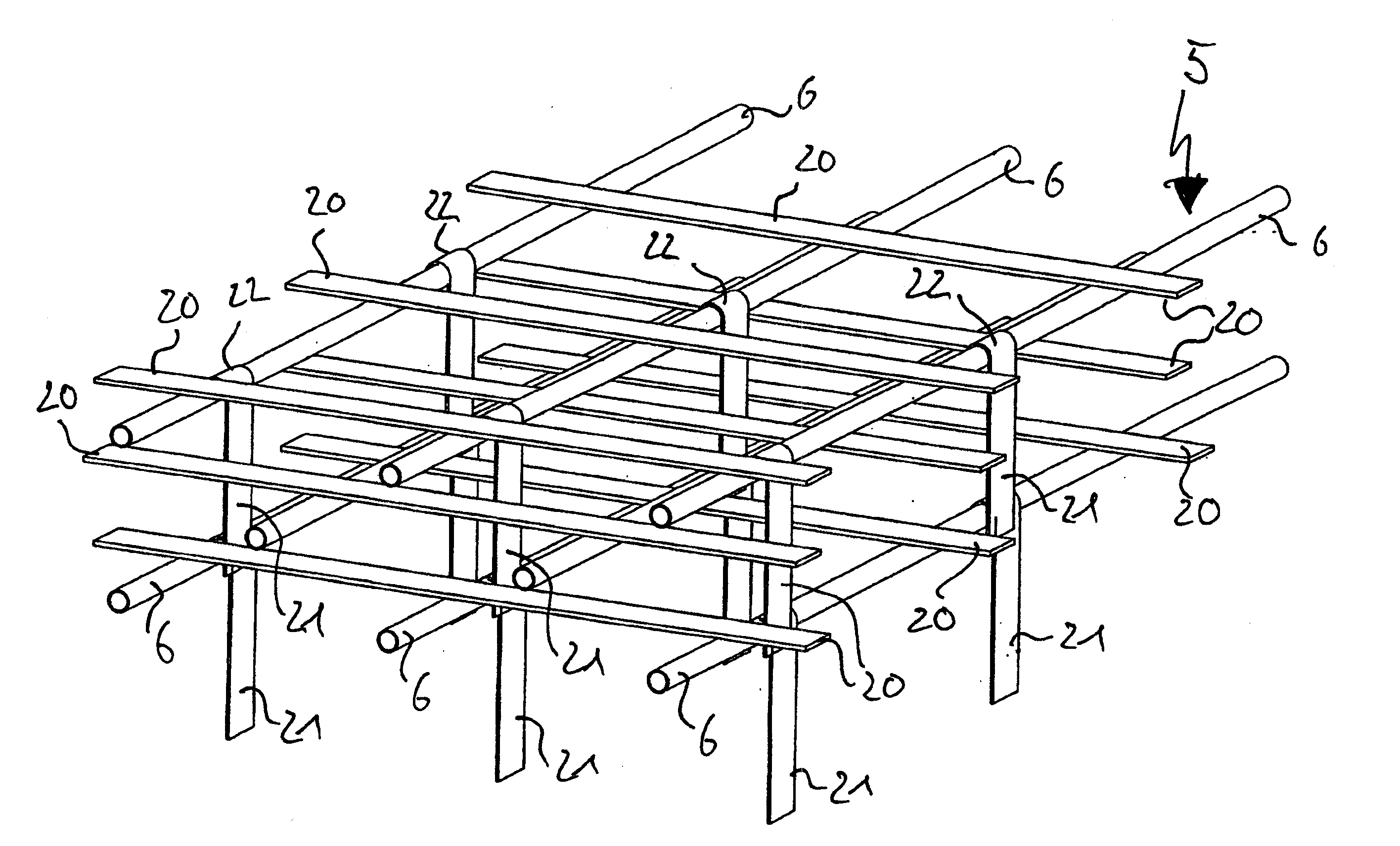
[0041]FIG. 4 shows heat conducting elements according to the invention in an oblique view of a partial detail of pipe system 5, whereby for a clearer illustration solid storage medium 2 itself is not shown. Seen are individual pipes 6 in horizontally stacked levels and running axis-parallel to one another, said pipes which are arranged from one level to another with a lateral offset in the height of half the mutual lateral distance, so that the distance between two individual pipes 6 is uniform at each place in solid storage medium 2. In addition, individual pipes 6 are mechanically decoupled from solid storage medium 2, for example, by sheathing with a graphite film (not shown).

[0042]Whereas primarily a heat distribution in solid storage medium 2 occurs in the axial direction in individual pipes 6 due to the energy transfer medium flowing therein, horizontal heat conducting elements 20 and vertical heat conducting elements 21 are provided for lateral distribution of the thermal ene...

second embodiment

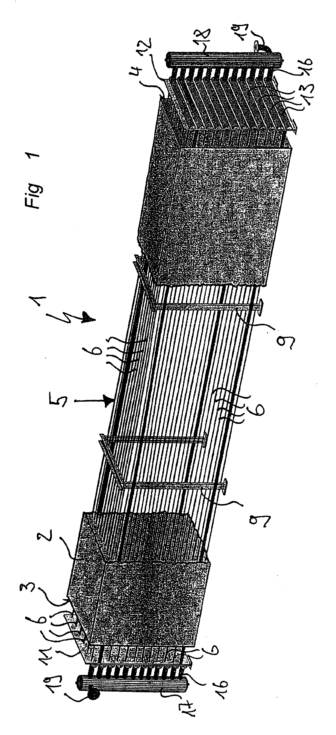
[0047]FIG. 5 shows a partial detail of a heat accumulator 1 of the invention. In this embodiment, solid storage medium 2 has prefabricated elements 23, which are placed one on top of another in horizontal layers 24 in a modular manner, whereby individual pipes 6 of pipe system 5 run in the horizontal butt joints of adjacent layers 24.

[0048]As already mentioned, only the functional principle of heat accumulator 1 is to be clarified with the type of presentation selected in FIG. 5, which is why only a small partial detail of heat accumulator 1 is shown. In reality, prefabricated elements 23, depending on the size of solid storage medium 2, extend over the entire width and / or length of solid storage medium 2 or only over a part thereof when a number of prefabricated elements 23 are strung together. The thickness of prefabricated elements 23 corresponds to the vertical distance of individual pipes 6 of pipe system 5.

[0049]Groove-shaped recesses 25 are formed in the top side of prefabric...


PUM


Abstract

A device for the intermediate storage of thermal energy and to a system comprising a plurality of such devices is provided. The device has a solids store and a pipe system, which is formed of individual pipes and runs through the solids store and through which an energy carrier medium flows. In order to be able to quickly and uniformly charge the solids store with thermal energy or discharge thermal energy therefrom, heat conducting elements are provided, each forming heat transmission regions with the individual pipes and each extending into the regions of the solids store that are free of individual pipes. The heat conducting elements also have a higher heat conductivity than the solids store.

Description

[0001]This nonprovisional application is a continuation of International Application No. PCT / EP2010 / 007909, which was filed on Dec. 23, 2010, and which claims priority to German Patent Application No. DE 10 2009 060 911.3, which was filed in Germany on Dec. 31, 2009, and which are both herein incorporated by reference.BACKGROUND OF THE INVENTION[0002]1. Field of the Invention[0003]The present invention relates to a device and system for the intermediate storage of thermal energy.[0004]2. Description of the Background Art[0005]In view of the dwindling primary raw materials worldwide as resources for energy production, regenerative and alternative concepts are becoming more and more important. Examples are the use of solar energy in solar thermal power plants or the use of waste heat from industrial manufacturing processes. Because these alternative forms of energy are coupled to solar radiation or to certain industrial processes, however, their continuous availability is not guarante...

Claims


Application Information

Patent Timeline
IPC IPC(8): F28D17/00
CPCF24D3/148F24D2220/10F24H7/02F28D20/0056F28F1/20Y02E60/142F28F13/00F28F21/02F28F21/04F28F21/08F28F9/0131Y02B30/00Y02E60/14
Inventor BAHL, CARSTENBROSIG, STEFANENOEKL, VIKTORLAING, DOERTEFISS, MICHAEL
Owner DEUTES ZENT FUER LUFT & RAUMFAHRT A V
Why Eureka
Try Eureka