
Systems and methods for co-production of geothermal energy and fluids

a technology of geothermal energy and co-production, applied in the field of systems and methods, can solve the problems of large heat loss of produced fluids, affecting the economic benefits of co-production, and wasting a large amount of thermal energy from oil and gas production to the atmospher

Active Publication Date: 2012-12-13
BLADE ENERGY PARTNERS
View PDF1 Cites 22 Cited by
  • Summary
  • Abstract
  • Description
  • Claims
  • Application Information

AI Technical Summary

Problems solved by technology

In typical hydrocarbon wells, resource temperature requirements may impose minimum depth and geothermal gradient constraints.
However, for fluid reservoirs with sufficient thermal energy potential, there will be a thermal energy price point at which thermal energy will (and should) influence the well design.
Currently the majority of thermal energy from oil and gas production is wasted to the atmosphere.
Unlike classical hydrothermal or even enhanced geothermal resources, co-produced oil and gas wells present more complicated economic considerations, given that economic value derives from both the hydrocarbons and heat energy recovered using a binary cycle at the surface.
Thus, the produced fluids are subject to significant heat loss in the wellbore, which worsens with decline in production rates.The composition and pressure of hydrocarbons being produced: as mentioned earlier, most oil and gas wells are designed with the intent of minimizing produced water rates, whereas geothermal energy, at least with binary cycles, will depend upon increased water rate.
This will add cost to the surface system.The loss of thermal energy if pre-exchange separation is required: if the binary plant cannot handle corrosive and sour produced fluids, separation may be required prior to entry into the plant.
This is bound to influence the overall well design, and hence the cost of well construction and operation.
Introducing thermal energy recovery as an additional design criterion complicates the well design and production decisions.
There is no simple set of formulas to determine the best solution when considering thermal energy recovery for a hydrocarbon recovery system.
The type of reservoir and hydrocarbon field development plan can also have a significant effect on the thermal energy recovery potential, since improved hydrocarbon recovery does not always imply improved thermal recovery.
Evaluating the appropriate design and the associated economics for well systems that involve the co-production of hydrocarbons and thermal energy is thus a complex problem.
In some cases maximizing the hydrocarbon production rate may not be the best way to optimize the overall energy recovery.
Although binary systems are fairly common in hydrothermal and enhanced geothermal system (EGS) projects, there are a few disadvantages when used in co-produced projects.
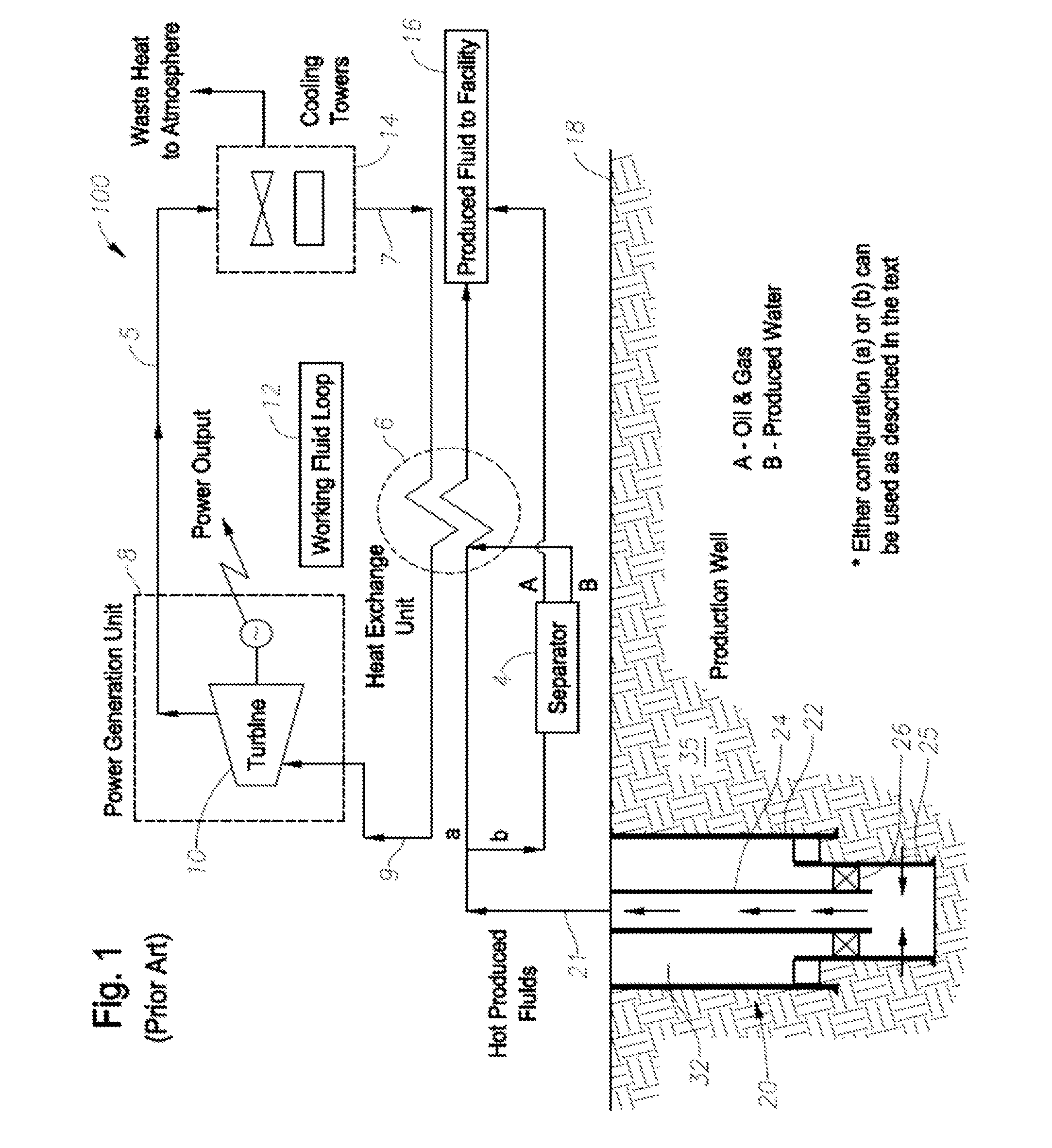
The main limitations when a binary cycle is used in a co-produced well are:production has to (usually) be dominated by water;non-sour, non-corrosive composition is desired, given equipment limitations; andproduction rate has to be very high to reduce wellbore heat loss and increase the net power generated.

Method used


Image

  • Systems and methods for co-production of geothermal energy and fluids
  • Systems and methods for co-production of geothermal energy and fluids
  • Systems and methods for co-production of geothermal energy and fluids

Examples


examples

Results and Discussion

[0152]Model Verification

[0153]In order to verify the model, results of the model were compared to those from, an industry-standard multiphase flow simulator known under the trade designation WELLFLO8. A standard production well was used for the comparison, with the following assumptions:[0154]Vertical Well[0155]Reservoir depth=10,000 ft[0156]Produced Fluid=Water[0157]Flowrate=10,000 BPD[0158]Bottomhole Temperature=260° F.[0159]Bottomhole Pressure=4150 psi[0160]Production through 7 inch, 32 ppf casing

[0161]Results of the comparison are illustrated in FIG. 4 and Table 1. As the results show, the comparison is excellent.

TABLE 1Exit temperature and pressure comparisonBGSWELLFLO 8Surface Temperature (° F.)245.4242.2Surface Pressure (psi)4858

[0162]The model was also verified against actual results from the Ormat binary power generating unit at the Rocky Mountain Oilfield Testing Center (RMOTC). The geometry and conditions were set to the data available on the RMOTC w...


PUM


Abstract

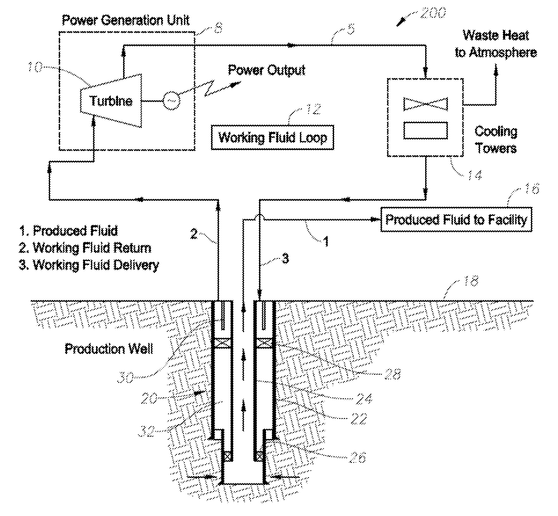
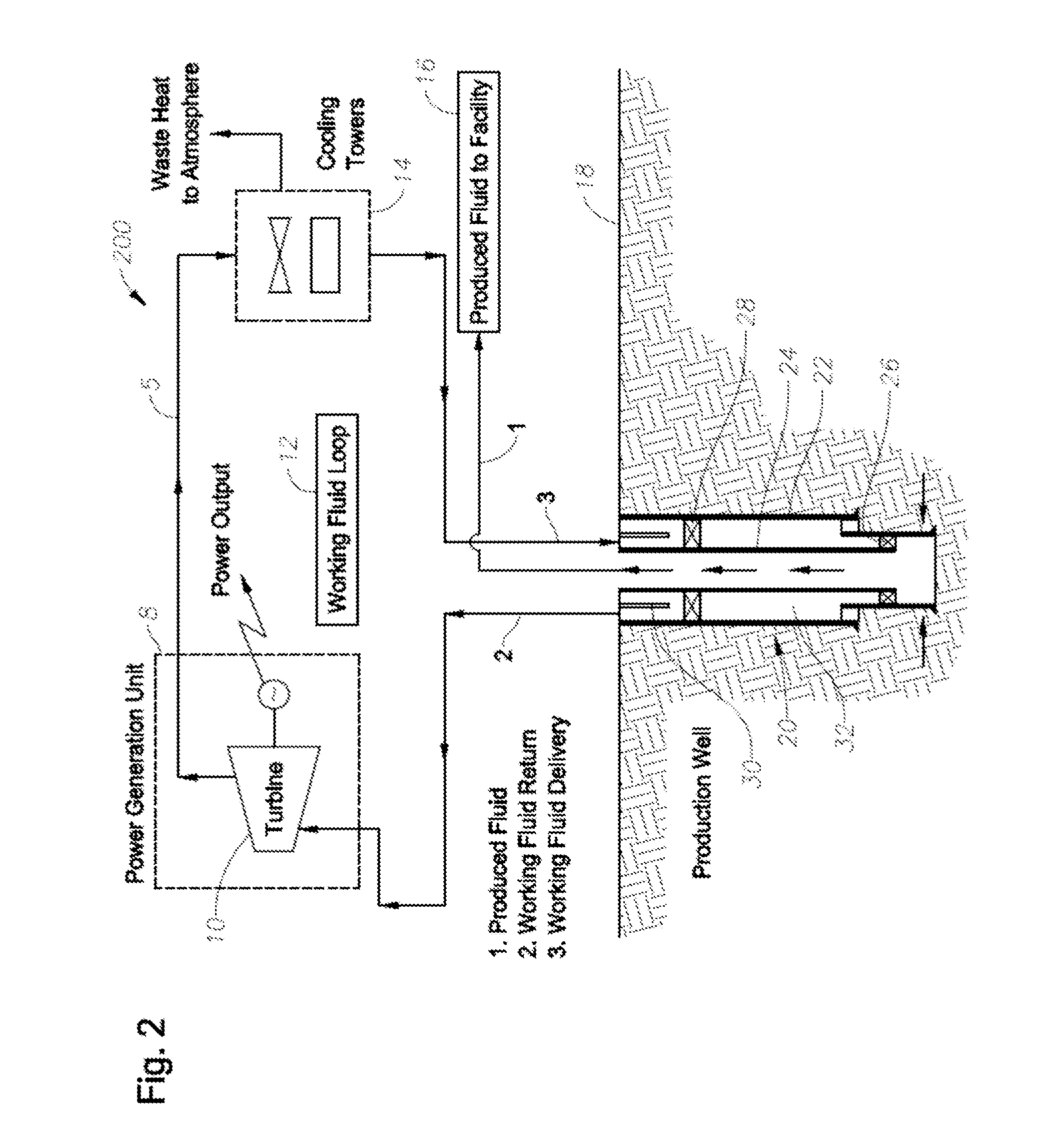
Systems include a well having a production casing and a production tubing positioned therein, forming an annulus there between. A packer is positioned in the annulus at a position sufficient to separate the annulus into a first portion and a second portion. The well further includes a tie-back conduit positioned in the first portion of the annulus and configured to allow heat transfer between a working fluid flowing through the first portion of the annulus and a production fluid flowing through the production tubing, thus separating the circulating working fluid from fluids in the second portion of the annulus. A working fluid loop is fluidly connected to the first portion of the annulus. Co-production methods, methods of modeling, and computer-readable media including the methods of modeling are disclosed.

Description

CROSS-REFERENCE TO RELATED APPLICATIONS[0001]This application claims domestic priority benefit under 35 U.S.C. §119(e) from applicants' provisional patent application Ser. No. 61 / 496,007, filed Jun. 12, 2011, which is incorporated herein by reference.BACKGROUND INFORMATION[0002]1. Technical Field[0003]The present disclosure relates in general to systems and methods useful in the production of energy. In particular, the present disclosure relates to systems and methods for production of energy from geothermal sources, as well as computer readable media for evaluating and / or comparing and / or simulating such systems and methods. The systems, methods, and computer readable media disclosed herein are useful in, for example, but not limited to, hydrocarbon exploration wells, production wells, well drilling, well completions, and well intervention.[0004]2. Background Art[0005]The thermal energy in co-produced oil and gas wells has been mentioned as a substantial resource for geothermal ene...

Claims


Application Information

Patent Timeline
Patent Type & Authority Applications(United States)
IPC IPC(8): E21B36/00E21B43/00G06F17/11E21B33/12
CPCF24J3/081Y02E10/16Y02E10/12F24J3/086F24T10/10F24T10/30F24T2201/00Y02E10/10G06F30/20
Inventor SURYANARAYANA, P. V.SACHDEVA, PARVEENCEYHAN, ISMAILRING, GARY ALLEN
Owner BLADE ENERGY PARTNERS
Learn More