Method for pilot assistance for the landing of an aircraft in restricted visibility

Inactive Publication Date: 2012-12-13
AIRBUS DEFENCE & SPACE
View PDF8 Cites 31 Cited by
  • Summary
  • Abstract
  • Description
  • Claims
  • Application Information

AI Technical Summary

Benefits of technology

[0016]Embodiments of the present invention provide a method for pilot assistance in particular for the above-described brown

Problems solved by technology

Helicopter landings in restricted visibility conditions represent an enormous physical and mental load for the pilots, and involve a greatly increased accident risk.
This applies in particular to night-time landings, landings in fog or snow fall, as well as landings in arid environments, which lead to so-called “brownout.” In this case, brownout means an effect which is caused by the rotor downwash of the helicopter and which can lead to complete loss of outside visibility within fractions of a second.
Investigations into the workload of pilots when landing in restrictive visibility conditions have shown that simultaneous coordination of the real outside view and two-dimensional symbols is difficult.
Under the stress which a landing such as this causes, particularly in military operational conditions, pilots therefore have a tendency to ignore individual display information items.
Furthermore, this known method describes a method for minimizing measurement errors, which lead to errors in the zymology display.
In this case, however, elevation errors and specification gaps when the database is used are not mentioned.
This has a negative effect on the workload and the necessary change to the standard approach process and makes use of nothing with respect to specific errors which are present in real systems (for example a sudden change in the position data when a GPS position update takes place).
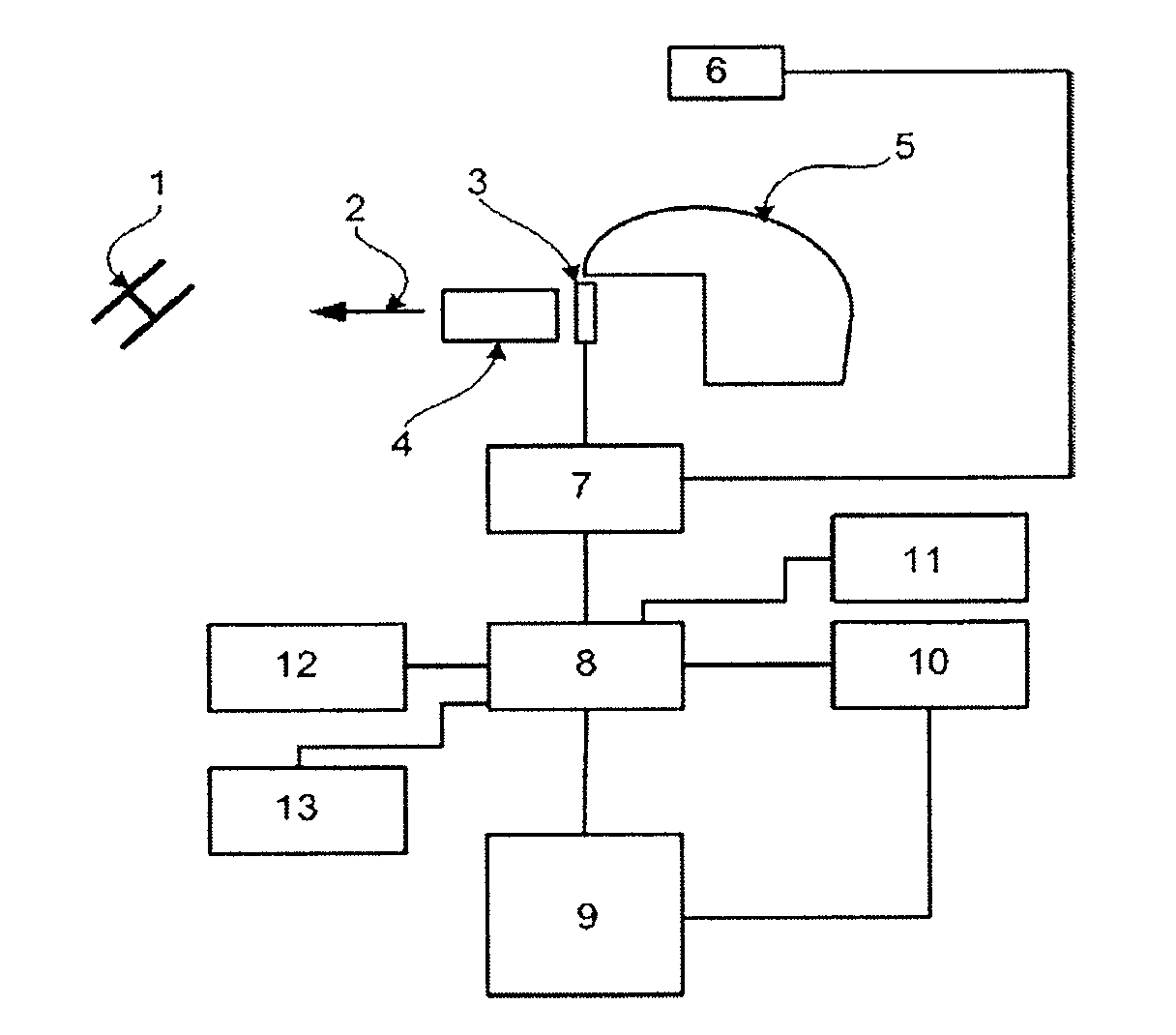
The technical complexity when using a range finder which, of course, must be aligned with the line of sight of the helmet sight system, i.e., it must be seated on a very precise platform which can be rotated on two a

Method used


Image

  • Method for pilot assistance for the landing of an aircraft in restricted visibility
  • Method for pilot assistance for the landing of an aircraft in restricted visibility
  • Method for pilot assistance for the landing of an aircraft in restricted visibility

Examples


Embodiment Construction

[0016]Embodiments of the present invention provide a method for pilot assistance in particular for the above-described brownout and whiteout scenarios, in which landing area zymology is displayed with high accuracy and using an up-to-date database.

[0017]Accordingly, embodiments can be directed to a method for pilot assistance for the landing of an aircraft in restricted visibility, with the position of the landing point being defined by a motion-compensated, aircraft-based helmet sight system during the landing approach, and with the landing point being displayed on a ground surface in the helmet sight system by the production of symbols which conform with the outside view. The method includes that the production or calculation of the ground surface is based on measurement data, produced during the approach, from an aircraft-based 3D sensor, and both the production of the 3D measurement data of the ground surface and the definition of the landing point are provided with reference to...


PUM


Abstract

Method for pilot assistance in landing an aircraft with restricted visibility, in which the position of a landing point is defined by at least one of a motion compensated, aircraft based helmet sight system and a remotely controlled camera during a landing approach, and with the landing point is displayed on a ground surface in the at least one of the helmet sight system and the remotely controlled camera by production of symbols that conform with the outside view. The method includes one of producing or calculating during an approach, a ground surface based on measurement data from an aircraft based 3D sensor, and providing both the 3D measurement data of the ground surface and a definition of the landing point with reference to a same aircraft fixed coordinate system.

Description

CROSS-REFERENCE TO RELATED APPLICATIONS[0001]The present application claims priority under 35 U.S.C. §119(a) of European Patent Application No. 11 004 366.8 filed May 27, 2011, the disclosure of which is expressly incorporated by reference herein in its entirety.BACKGROUND OF THE INVENTION[0002]Helicopter landings in restricted visibility conditions represent an enormous physical and mental load for the pilots, and involve a greatly increased accident risk. This applies in particular to night-time landings, landings in fog or snow fall, as well as landings in arid environments, which lead to so-called “brownout.” In this case, brownout means an effect which is caused by the rotor downwash of the helicopter and which can lead to complete loss of outside visibility within fractions of a second. A similar effect occurs during landings on loose snow, and this is referred to as “whiteout.” Assistance systems for the risk scenarios mentioned above are in general intended to be designed su...

Claims


Application Information

Patent Timeline
IPC IPC(8): H04N13/02G01S13/935
CPCG01C23/005G01S7/062G01S13/94G01S7/24G01S7/51G01S7/22G01S13/935G05D1/0676
Inventor MUENSTERER, THOMASKIELHORN, PETERWEGNER, MATTHIAS
Owner AIRBUS DEFENCE & SPACE
Why Eureka
Try Eureka