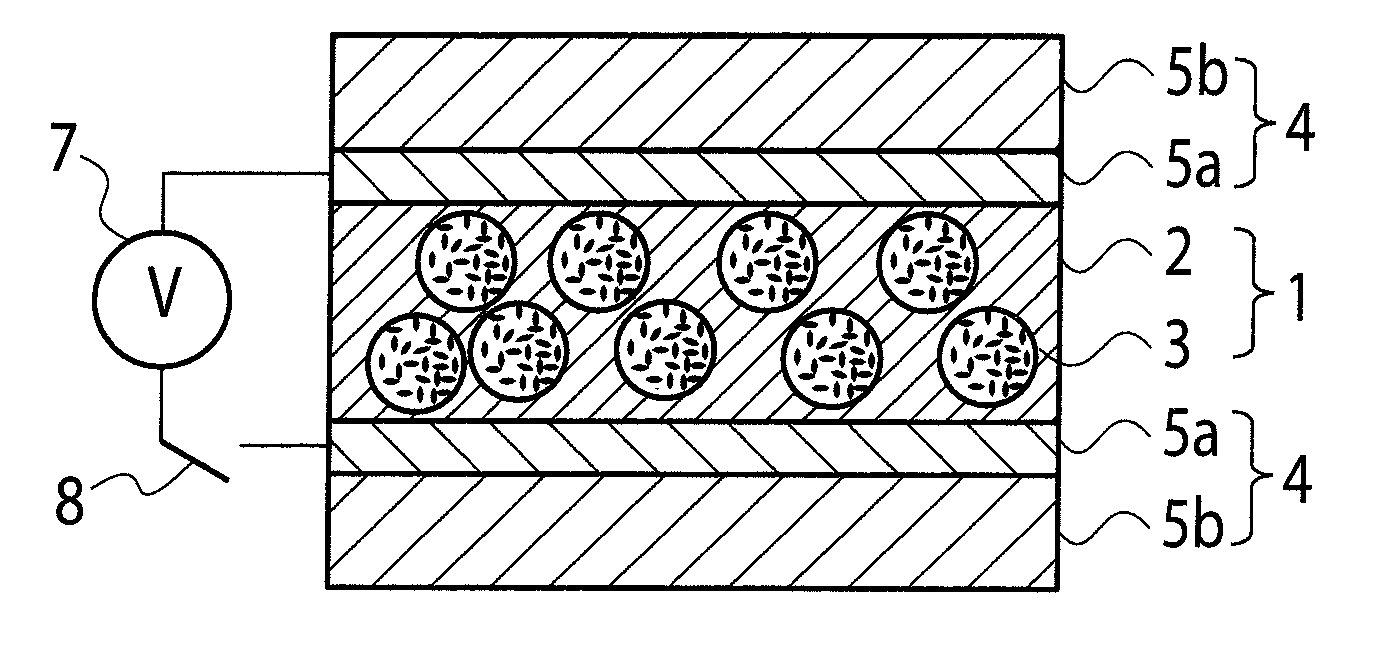
Light control film

a technology of light control and film, applied in the field of light control film, can solve the problems of color phase change, change in optical density, and practical use, and achieve the effect of excellent radio wave transparency

Active Publication Date: 2012-12-13
RESONAC CORP
View PDF9 Cites 6 Cited by
  • Summary
  • Abstract
  • Description
  • Claims
  • Application Information

AI Technical Summary

Benefits of technology

[0031]The light control film of the present invention has excellent radio wave transparency, so that even inside a space surrounded by the light control film, television sets, mobile telephones, remote control devices utilizing radio waves, and the like can be made to function adequately. Furthermore, when a particular organic binder resin is used, the adhesiveness between the transparent resin substrate and the transparent conductive layer of the transparent conductive resin substrate can be made satisfactory.
[0032]The disclosure of the present application relates to the subject matters described Japanese Patent Application No. 2010-14191 filed on Jan. 26, 2010, the disclosure of which is incorporated herein by reference.

Problems solved by technology

However, such an initial light control apparatus had problems in practical use, such as the aggregation of the light control particles inside the light control suspension, sedimentation due to their own weights, color phase change due to heat, changes in the optical density, deterioration caused by ultraviolet ray irradiation, difficulties in keeping up the gap between the substrates and in the injection of the light control suspension into the gap, and others.
Accordingly, it was difficult to put the light control apparatus to practical use.
However, since even these light control glasses also have a structure in which a liquid light control suspension is encapsulated in a gap between two transparent conductive substrates as in the case of conventional light control glasses, there is a problem that, in the case of the manufacture of large-sized products, uniform encapsulation of the suspension in the gap between the two transparent conductive substrates is difficult, and a swelling phenomenon in the lower part is likely to occur due to the difference in the hydraulic pressure between the upper part and the lower part of the product.
Furthermore, when the gap between the substrates is changed due to the external environment, for example, the pressure of wind, the optical density is changed as a result, so that the color phase becomes inhomogeneous, Further, there is a problem that the sealing material in the peripheral area for holding a liquid between the transparent conductive substrates is destroyed, and the light control material leaks out.
In addition, unevenness occurs in the response time as a result of deterioration by ultraviolet ray, and a decrease in the voltage between the peripheral areas and the center of the transparent conductive substrates.
Furthermore, in a space surrounded by the light control glasses used heretofore, since the transparent conductive resin substrates used in the glasses have small surface resistivity and low radio wave transparency, there is a problem that television sets, mobile telephones, remote control devices utilizing radio waves, and the like may not function adequately.

Method used


Image

  • Light control film
  • Light control film
  • Light control film

Examples


example 1

[0209]2.5 g of the light control suspension obtained in the (Preparation Example for light control suspension) was added to 10 g of the energy-beam-curable silicone resin obtained in the (Production Example for energy-beam-curable silicone resin), 0.2 g of bis(2,4,6-trimethylbenzoyl)phenylphosphine oxide (manufactured by Ciba Specialty Chemicals Corp.) as a photopolymerization initiator, and 0.3 g of dibutyltin dilaurate as a coloration preventing agent. The mixture was mechanically mixed for one minute, and thus a light control material was produced.

[0210]For the transparent conductive layer, polystyrenesulfonic acid-doped poly(3,4-ethylenedioxythiophene) (CLEVIOS S V3, manufactured by H.C. Starck GmbH, having a structural unit represented by polystyrenesulfonic acid (upper part of the above formula a), weight average molecular weight: 40,000, thiophene unit: 5- to 10-mer) as a conductive polymer, and pentaerythritol triacrylate (trade name: ARONIX M-305, manufactured by Toagosei C...

example 2

[0223]A light control film was produced in the same manner as in Example 1, except that the gap of the applicator at the time of applying the transparent conductive layer was set to 5 μm, and the light control film was evaluated in the same manner as in Example 1.

[0224]The surface resistivity of the transparent conductive layer was 1450Ω / □.

example 3

)

[0225]A light control film was produced in the same manner as in Example 1, except that the gap of the applicator at the time of applying the transparent conductive layer was set to 3 μm, and the light control film was evaluated in the same manner as in Example 1.

[0226]The surface resistivity of the transparent conductive layer was 1850Ω / □.


PUM

PropertyMeasurementUnit
radio wave shielding propertyaaaaaaaaaa
frequencyaaaaaaaaaa
optical densityaaaaaaaaaa

Abstract

Disclosed is a light control film comprising: two of transparent conductive resin substrates each having a transparent conductive layer and a transparent resin substrate; and a light control layer interposed between the two transparent conductive resin substrates to be in contact with the transparent conductive layer sides, the light control layer containing: a resin matrix; and a light control suspension dispersed in the resin matrix, wherein the transparent conductive layer contains: an organic binder resin; and a conductive polymer. The present invention can provide a light control film having satisfactory adhesiveness between the light control layer and the transparent conductive layer and having excellent radio wave transparency.

Description

TECHNICAL FIELD[0001]The present invention relates to a light control film having a light control function.BACKGROUND ART[0002]A light control glass containing a light control suspension was first invented by Edwin Land, and the light control glass is in the form of a structure in which a liquid-state light control suspension is inserted between two of transparent conductive substrates having a narrow gap therebetween (see, for example, Patent Documents 1 and 2). According to the invention by Edwin land, the liquid-state light control suspension inserted between the two transparent conductive substrates is such that when an electric field is not applied, as a result of the Brownian motion of light control particles that are dispersed in the suspension, most of the incident light rays are reflected, scattered or absorbed by the light control particles, and only a very small portion is transmitted.[0003]That is, the extent of transmission, reflection, scattering or absorption can be d...

Claims


Application Information

Patent Timeline
Patent Type & Authority Applications(United States)
IPC IPC(8): G02F1/167
CPCC08G2261/3223C08G2261/51C08G2261/794C08L65/00C08G18/3206G02F1/172C08G18/673C08G18/755C09D4/06
Inventor NOMURA, SATOYUKIMORISHITA, YOSHIITANAKA, TOORU
Owner RESONAC CORP
Why Eureka
Try Eureka