Light control film

a technology of light control film and film film, applied in vehicle components, antiglare equipment, instruments, etc., can solve the problems of color phase change, change in optical density, and inability to control the light intensity, and achieve excellent radio wave transparency, small in-plane fluctuation of the surface resistivity of the transparent conductive layer, and stable driving

Inactive Publication Date: 2014-03-25
RESONAC CORPORATION
View PDF26 Cites 0 Cited by
  • Summary
  • Abstract
  • Description
  • Claims
  • Application Information

AI Technical Summary

Benefits of technology

[0033]The light control film of the present invention is driven stably because the in-plane fluctuation of the surface resistivity of the transparent conductive layer is small, and also has excellent radio wave transparency, so that even inside a space surrounded by the light control film, television sets, mobile telephones, remote control devices utilizing radio waves, and the like can be made to function adequately.
[0034]Furthermore, when a particular organic binder resin is used, the adhesiveness between the transparent conductive layer and the transparent resin substrate of the transparent conductive resin substrate can be made satisfactory.
[0035]The disclosure of the present application relates to the subject matter described in Japanese Patent Application No. 2010-14200 filed on Jan. 26, 2010, the disclosure of which is incorporated herein by reference.

Problems solved by technology

However, such an initial light control apparatus had problems in practical use, such as the aggregation of the light control particles inside the light control suspension, sedimentation due to their own weights, color phase change due to heat, changes in the optical density, deterioration caused by ultraviolet ray irradiation, difficulties in keeping up the gap between the substrates and in the injection of the light control suspension into the gap, and others.
Accordingly, it was difficult to put the light control apparatus to practical use.
However, since even these light control glasses also have a structure in which a liquid light control suspension is encapsulated in a gap between two transparent conductive substrates as in the case of conventional light control glasses, there is a problem that, in the case of the manufacture of large-sized products, uniform encapsulation of the suspension in the gap between the two transparent conductive substrates is difficult, and a swelling phenomenon in the lower part is likely to occur due to the difference in the hydraulic pressure between the upper part and the lower part of the product.
Further, there is a problem that the sealing material in the peripheral area for holding a liquid between the transparent conductive substrates is destroyed, and the light control material leaks out.
In addition, unevenness occurs in the response time as a result of deterioration by ultraviolet ray, and a decrease in the voltage between the peripheral areas and the center of the transparent conductive substrates.
Furthermore, in a space surrounded by the light control glasses used heretofore, since the transparent conductive resin substrates used in the glasses have small surface resistivity and low radio wave transparency, there is a problem that television sets, mobile telephones, remote control devices utilizing radio waves, and the like may not function adequately.

Method used


Image

  • Light control film
  • Light control film
  • Light control film

Examples


example 1

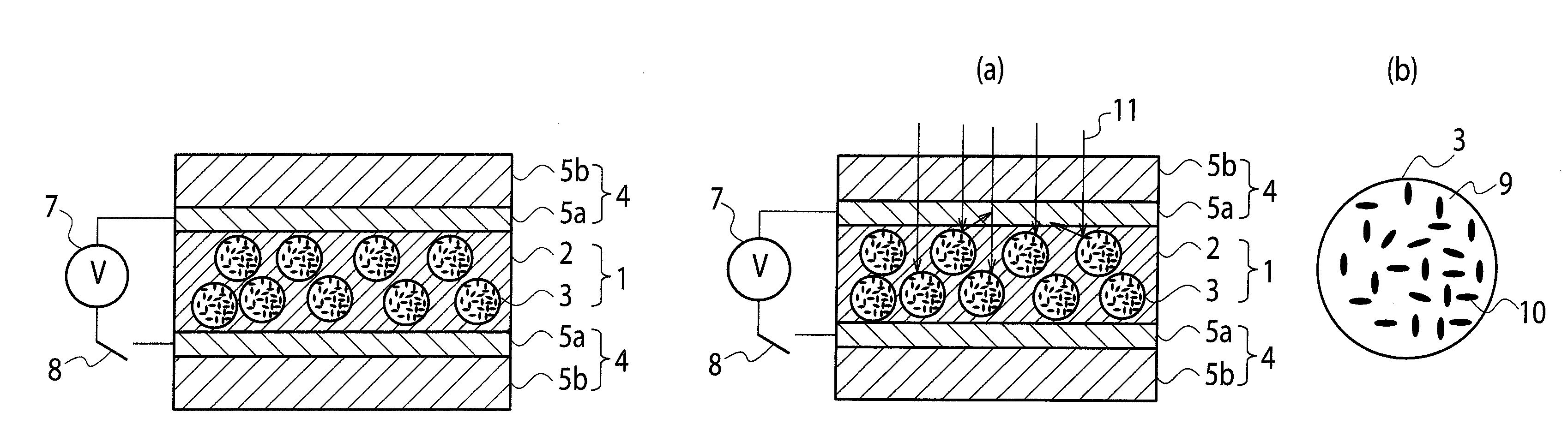
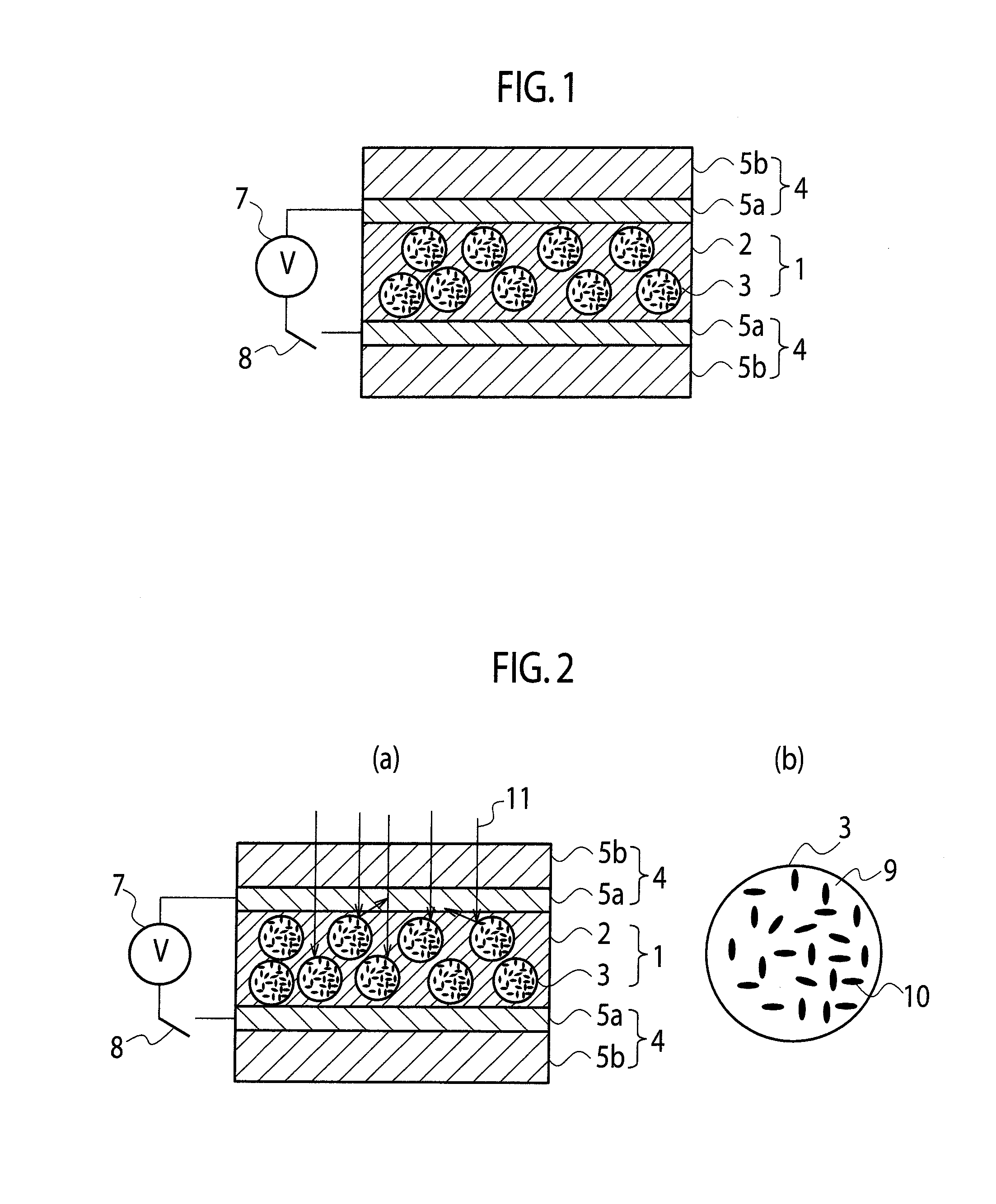
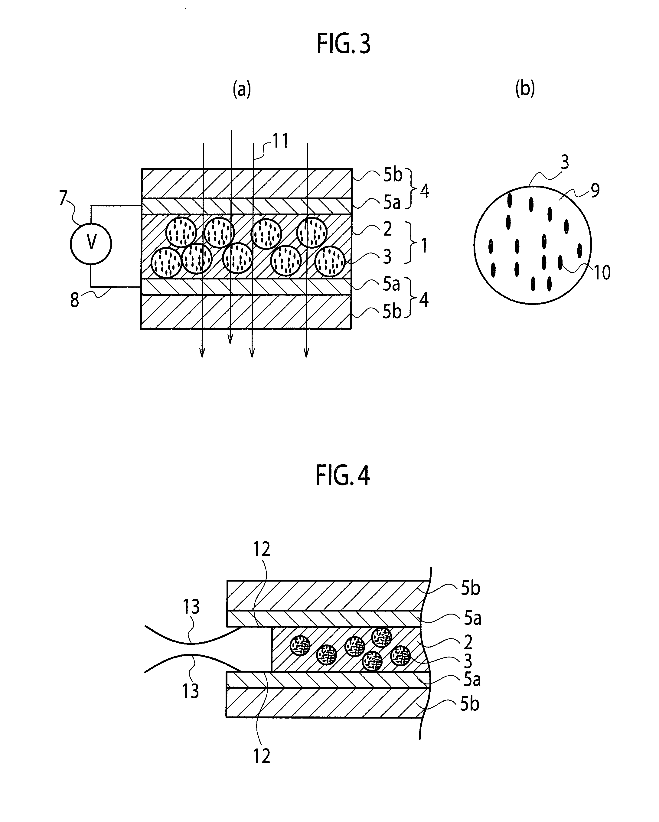
[0209]2.5 g of the light control suspension obtained in the (Preparation Example for light control suspension) was added to 10 g of the energy-beam-curable silicone resin obtained in the (Production Example for energy-beam-curable silicone resin), 0.2 g of bis(2,4,6-trimethylbenzoyl)phenylphosphine oxide (manufactured by Ciba Specialty Chemicals Corp.) as a photopolymerization initiator, and 0.3 g of dibutyltin dilaurate as a coloration preventing agent. The mixture was mechanically mixed for one minute, and thus a light control material was produced.

[0210]Meanwhile, for the transparent conductive layer, an ITO powder (manufactured by Dowa Holdings Co., Ltd., average particle size: 30 nm) and a mixture of pentaerythritol triacrylate and pentaerythritol tetraacrylate (trade name: ARONIX M-305, manufactured by Toagosei Co., Ltd.) were mixed at proportions of 75% by mass and 25% by mass, respectively, and this mixture was dispersed in a solvent mixture of methyl ethyl ketone:cyclohexan...

example 2

[0225]A light control film was produced in the same manner as in Example 1, except that an ITO powder (manufactured by Dowa Holdings Co., Ltd., average particle size: 30 nm) and a mixture of pentaerythritol triacrylate and pentaerythritol tetraacrylate (trade name: ARONIX M-305, manufactured by Toagosei Co., Ltd.) were mixed at proportions of 80% by mass and 20% by mass, respectively, and the light control film was evaluated in the same manner as in Example 1. At this time, a photopolymerization initiator (1-hydroxycyclohexyl phenyl ketone) was added in an amount of 3% by mass based on ARONIX M-305. The thickness of the transparent conductive layer after curing was 1.0 μm.

[0226]The surface resistivity of the transparent conductive layer was 1800Ω / □.

[0227]The light transmittance of the transparent conductive resin substrate was 84%.

example 3

[0228]A light control film was produced in the same manner as in Example 1, except that an ITO powder (manufactured by Dowa Holdings Co., Ltd., average particle size: 30 nm) and a mixture of pentaerythritol triacrylate and pentaerythritol tetraacrylate (trade name: ARONIX M-305, manufactured by Toagosei Co. Ltd.) were mixed at proportions of 85% by mass and 15% by mass, respectively, and the light control film was evaluated in the same manner as in Example 1. At this time, a photopolymerization initiator (1-hydroxycyclohexyl phenyl ketone) was added in an amount of 3% by mass based on ARONIX M-305. The thickness of the transparent conductive layer after curing was 1.1 μm.

[0229]The surface resistivity of the transparent conductive layer was 1300Ω / □.

[0230]The light transmittance of the transparent conductive resin substrate was 85%.


PUM

PropertyMeasurementUnit
radio wave shielding propertyaaaaaaaaaa
frequencyaaaaaaaaaa
optical densityaaaaaaaaaa

Abstract

Disclosed is a light control film comprising: two of transparent conductive resin substrates each having a transparent conductive layer and a transparent resin substrate; and a light control layer interposed between the two transparent conductive resin substrates to be in contact with the transparent conductive layer sides, the light control layer containing: a resin matrix; and a light control suspension dispersed in the resin matrix, wherein: the transparent conductive layer contains an organic binder resin, and conductive particles dispersed in the organic binder resin, the mass ratio of the organic binder resin and the conductive particles is 50 / 50 to 10 / 90, and the entirety or a portion of the organic binder resin is composed of (meth)acrylate containing a hydroxyl group. The present invention can provide a light control film having excellent radio wave transparency and having satisfactory adhesiveness between the light control layer and the transparent conductive layer.

Description

TECHNICAL FIELD[0001]The present invention relates to a light control film having a light control function.BACKGROUND ART[0002]A light control glass containing a light control suspension was first invented by Edwin Land, and the light control glass is in the form of a structure in which a liquid-state light control suspension is inserted between two of transparent conductive substrates having a narrow gap therebetween (see, for example, Patent Documents 1 and 2). According to the invention by Edwin land, the liquid-state light control suspension inserted between the two transparent conductive substrates is such that when an electric field is not applied, as a result of the Brownian motion of light control particles that are dispersed in the suspension, most of the incident light rays are reflected, scattered or absorbed by the light control particles, and only a very small portion is transmitted.[0003]That is, the extent of transmission, reflection, scattering or absorption can be d...

Claims


Application Information

Patent Timeline
Patent Type & Authority Patents(United States)
IPC IPC(8): G02B26/00G09G3/34
CPCG02F2202/36B60J3/04G02F2202/023G02F1/172G02F2201/12
Inventor NOMURA, SATOYUKIMORISHITA, YOSHIITANAKA, TOORU
Owner RESONAC CORPORATION
Why Eureka
Try Eureka