Catheter with enhanced pushability

Inactive Publication Date: 2012-12-13
ABBOTT LAB VASCULAR ENTERPRISE
View PDF28 Cites 9 Cited by
  • Summary
  • Abstract
  • Description
  • Claims
  • Application Information

AI Technical Summary

Benefits of technology

[0012]In view of the foregoing, it is an object of the present invention to provide apparatus that increases the push force transmitt

Problems solved by technology

One problem associated with the use of balloon catheters is that kinks may develop along the catheter.
Because the catheter must be relatively flexible to be advanced through tortuous vasculature, a flexible catheter is prone to kink when pushed from its proximal end by the physician.
One drawback associated with the catheter described in the Horzewski patent is the potential for kinks to develop at the distal end of the catheter, i.e., near the balloon.
The stiff proximal section may be readily advanced, but the location where the soft distal portion joins the stiff proximal section may be particularly susceptible to kinking.
This adverse event is especially likely to occur

Method used


Image

  • Catheter with enhanced pushability
  • Catheter with enhanced pushability
  • Catheter with enhanced pushability

Examples


Embodiment Construction

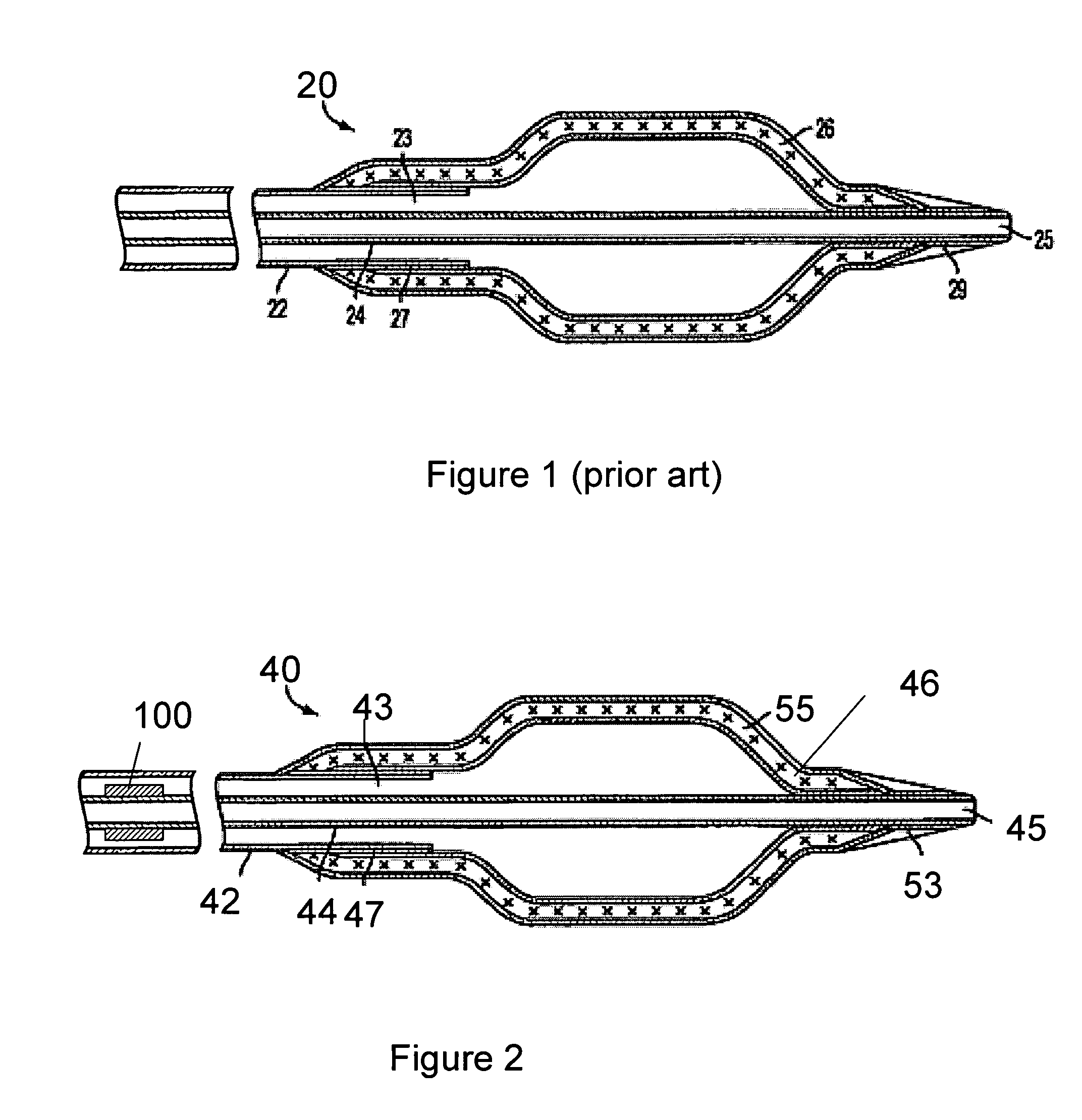
[0025]Referring to FIG. 1, a previously-known balloon catheter from U.S. Pat. No. 5,492,532 to Ryan et al. (Ryan) is described. Catheter 20 comprises outer tube 22, inner tube 24, and balloon 26 having proximal and distal ends, the proximal end of balloon 26 being affixed to outer tube 22 at proximal affixation point 27 and distally affixed to inner tube 24 at point 29. Outer tube 22 and inner tube 24 are provided in a coaxial alignment, such that inflation lumen 23 communicates with balloon 26 while guidewire lumen 25 allows catheter 20 to be advanced over a guidewire. Catheter 20 comprises proximal and distal ends, of which the distal end is depicted in FIG. 1. The proximal end of catheter 20 communicates with a traditional proximal hub assembly (not shown) that comprises a proximal guidewire entry port and an inflation / deflation port. The apparatus further may comprise radiopaque markers (not shown) affixed to inner tube 24 and disposed within balloon segment 26.

[0026]One drawbac...


PUM


Abstract

Apparatus for enhancing pushability and minimizing kinking of a balloon catheter is provided, wherein a catheter comprises inner and outer tubes, and a balloon that is proximally affixed to the outer tube and distally affixed to the inner tube. The catheter of the present invention further comprises a tubular member imposed on the inner tube which is configured to form a reversible mechanical linkage between inner tube and outer tube while an axially compressive load is applied to the catheter tip.

Description

FIELD OF THE INVENTION[0001]The present invention relates to a medical catheter, and more particularly, a balloon catheter having a reinforcing segment to facilitate catheter pushability and minimize kinking, balloon buckling and bunching.BACKGROUND OF THE INVENTION[0002]Angioplasty and stenting are widely used techniques for treating vascular disease. In balloon angioplasty, a catheter having an inflatable balloon affixed to its distal end is guided through a patient's vasculature with the balloon in a deflated state, and the balloon is positioned within a vascular lesion. The balloon then is inflated to compress the atherosclerotic plaque against the vessel wall to restore adequate blood flow in the vessel. Stenting involves the deployment of small tubular prostheses, either balloon expanded or self-expanding, that radially expand to maintain vessel patency, and are commonly used in conjunction with balloon angioplasty.[0003]One problem associated with the use of balloon catheters...

Claims


Application Information

Patent Timeline
IPC IPC(8): A61B17/22A61F2/958
CPCA61M25/005A61M2025/0059A61M25/1006A61M25/0051
Inventor JEFFREY, ANDREWLACKEN, JOHN P.
Owner ABBOTT LAB VASCULAR ENTERPRISE
Why Eureka
Try Eureka