
Apparatus for manufacturing vitreous silica crucible

a technology of vitreous silica and crucible, which is applied in the field of apparatus for manufacturing vitreous silica crucible, can solve the problems of difficult stably manufacturing high-quality vitreous silica crucible, unstable raw silica powder, etc., and achieves the effects of high quality, reduced current fluctuations, and uniform thickness

Inactive Publication Date: 2012-12-20
JAPAN SUPER QUARTZ CORP
View PDF4 Cites 7 Cited by
  • Summary
  • Abstract
  • Description
  • Claims
  • Application Information

AI Technical Summary

Benefits of technology

This solution enables the stable production of high-quality vitreous silica crucibles with uniform thickness and low bubble content by continuously adjusting the power supply to maintain consistent heat generation, reducing weight non-uniformity and improving the inner surface properties.

Problems solved by technology

As a result, a molten state of raw silica powder is not stable, and thus it is difficult to stably manufacture a high quality vitreous silica crucible having a transparent vitreous silica layer with a uniform thickness and a significantly small number of bubbles.

Method used


Image

  • Apparatus for manufacturing vitreous silica crucible
  • Apparatus for manufacturing vitreous silica crucible
  • Apparatus for manufacturing vitreous silica crucible

Examples


first embodiment

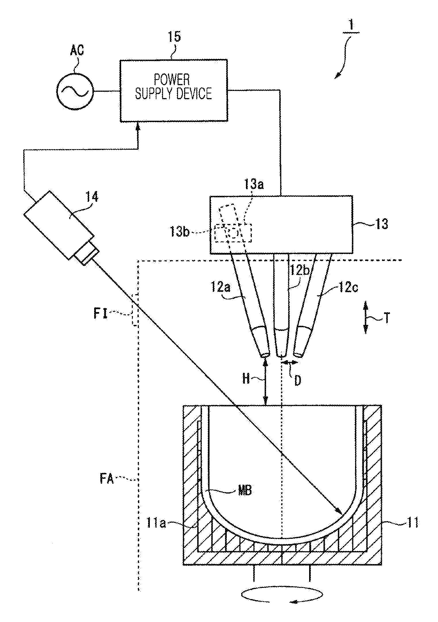
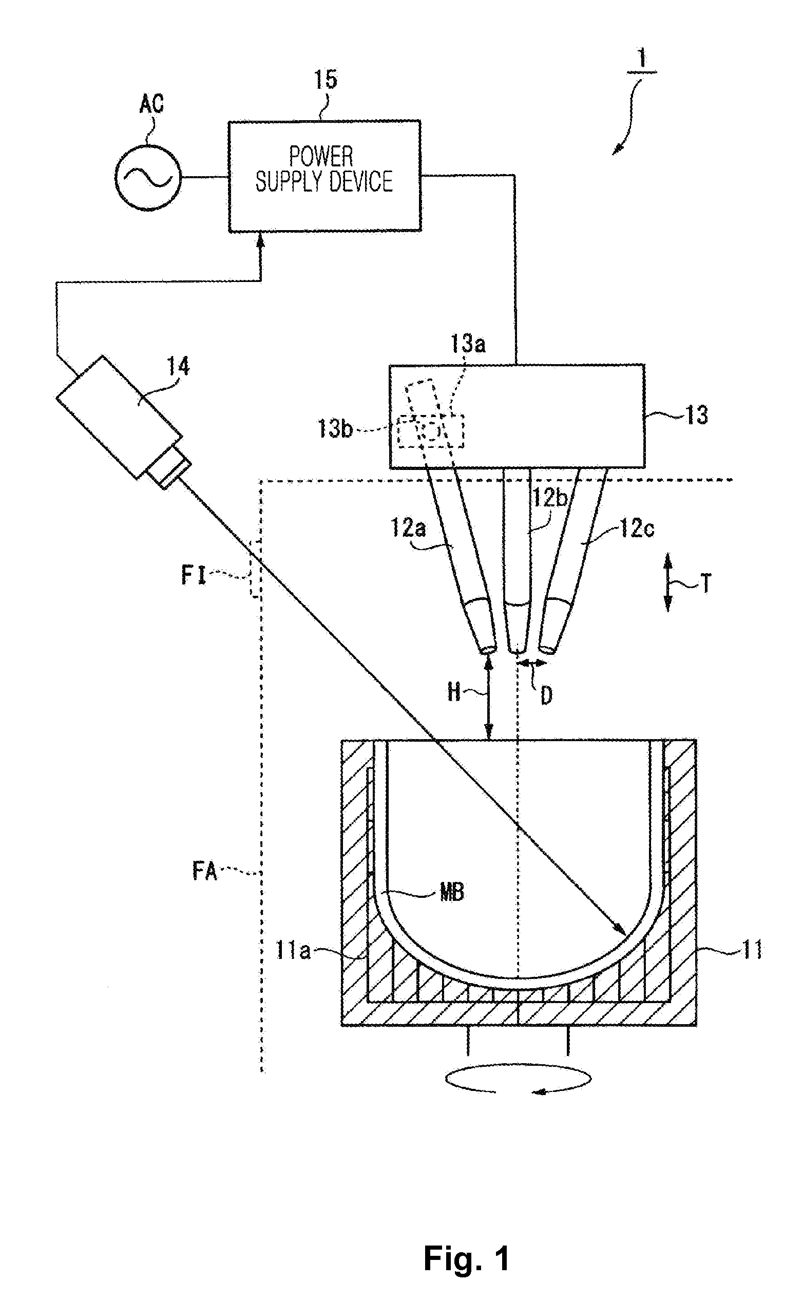
[0045]FIG. 1 is a diagram schematically showing an apparatus for manufacturing a vitreous silica crucible according to a first embodiment of the present invention. As shown in FIG. 1, the apparatus 1 for manufacturing a vitreous silica crucible includes a spinning mold (a mold) 11, carbon electrodes 12a, 12b, and 12c (electrodes), an electrode position setting unit 13, a radiation thermometer 14 (a temperature detector), and a power supply device 15. The apparatus 1 manufactures a vitreous silica crucible having a transparent vitreous silica layer formed inside an opaque vitreous silica layer by fusing silica powder deposited in the mold 11 through an arc discharge and holding the molten silica under depressurized conditions.

[0046]The mold 11 defines a shape of a vitreous silica crucible to be manufactured, is formed of carbon or the like, and is housed in an arc furnace FA, where the mold 11 may be rotated by a rotation unit (not shown). Silica powder molded body MB is formed by su...

second embodiment

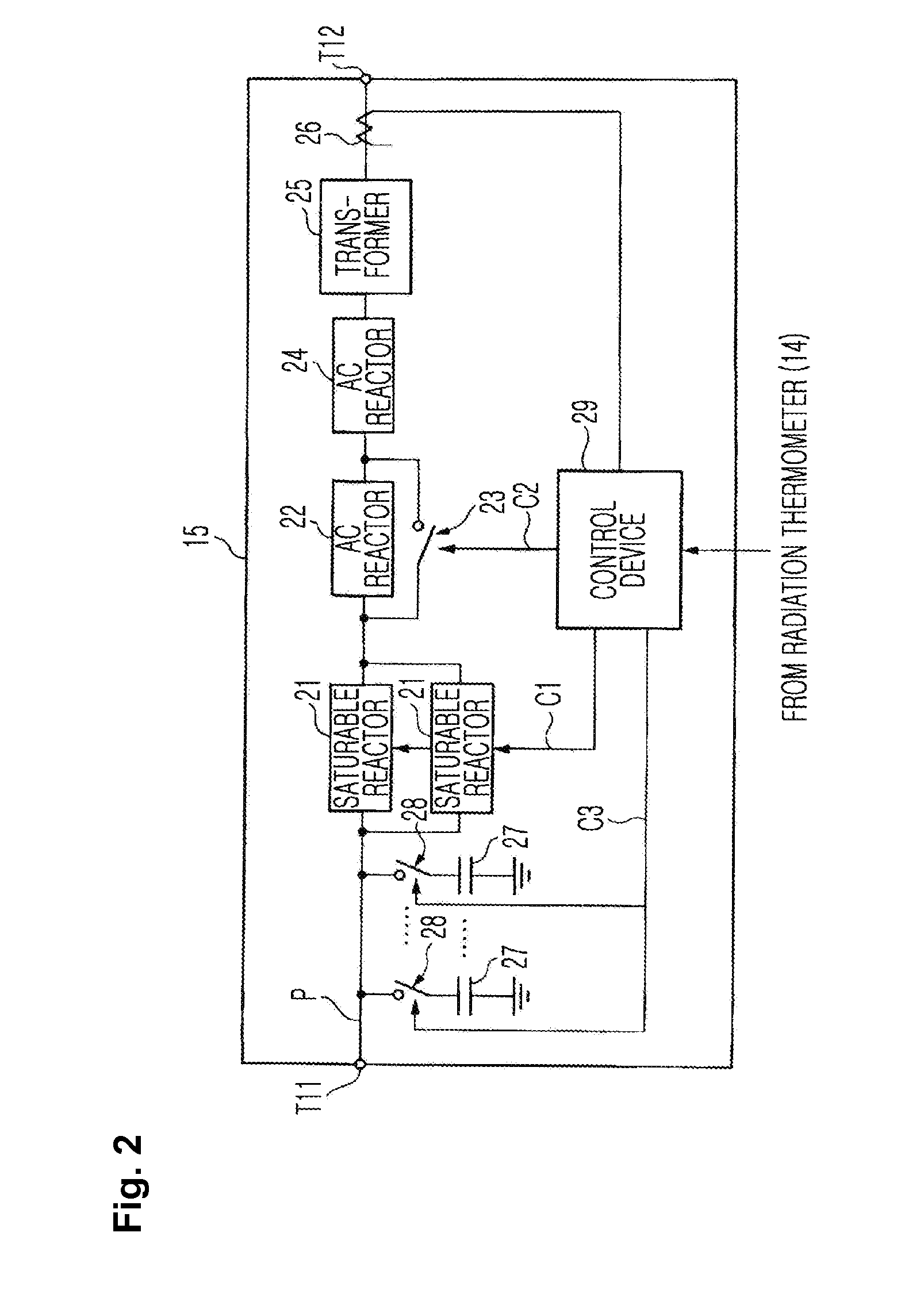
[0073]Next, an apparatus for manufacturing a vitreous silica crucible according to a second embodiment of the present invention will be described in detail. The overall configuration of the apparatus for manufacturing a vitreous silica crucible according to the present embodiment is identical to the apparatus 1 for manufacturing a vitreous silica crucible according to the first embodiment shown in FIG. 1 and includes the components from the mold 11 through to the power supply device 15. However, the apparatus for manufacturing a vitreous silica crucible according to the present embodiment has a power supply device having a different configuration from the power supply device (the power supply device 15 shown in FIG. 2) of the apparatus for manufacturing a vitreous silica crucible according to the first embodiment of the present invention.

[0074]FIG. 5 is a block diagram showing configurations of the major components of a power supply device included in the apparatus for manufacturing...


PUM

PropertyMeasurementUnit
thicknessaaaaaaaaaa
currentaaaaaaaaaa
diameteraaaaaaaaaa

Abstract

Provided is an apparatus for manufacturing a vitreous silica crucible, which is capable of stably manufacturing a high quality vitreous silica crucible by stabilizing heat generation through an arc discharge. The apparatus for manufacturing a vitreous silica crucible includes a mold that defines a shape of a vitreous silica crucible, carbon electrodes that generate an arc discharge for fusing a silica powder molded body formed in the mold, and a power supply device that supplies power to the carbon electrodes. The power supply device includes a saturable reactor that is provided on a supply path of the power to the carbon electrodes and has variable reactance, and a control device that controls the power supplied to the carbon electrodes by changing the reactance of the saturable reactor.

Description

[0001]This application is a division of U.S. patent application Ser. No. 13 / 095,472 filed Apr. 27, 2011, which is incorporated herein by reference in its entirety.BACKGROUND OF THE INVENTION[0002]1. Field of the Invention[0003]The present invention relates to an apparatus for manufacturing a vitreous silica crucible used for fabrication of silicon single crystal or the like.[0004]2. Description of Related Art[0005]The Czochralski method is one of the most popular methods of fabricating silicon single crystal. The Czochralski method is a method of fabricating silicon single crystal by forming silicon melt by heating polycrystalline silicon housed in a vitreous silica crucible by using a heater and growing high purity silicon single crystal to be a seed crystal, by dipping high purity single crystalline silicon into the silicon melt and pulling up the high purity single crystalline silicon. If a vitreous silica crucible containing an impurity is used in the fabrication of silicon sing...

Claims


Application Information

Patent Timeline
Patent Type & Authority Applications(United States)
IPC IPC(8): C03B20/00
CPCC03B19/095
Inventor SUDO, TOSHIAKIKISHI, HIROSHIFUJITA, TAKESHIKANDA, MINORU
Owner JAPAN SUPER QUARTZ CORP
Learn More