

Photovoltaic module with chlorosulfonated polyolefin layer
a photovoltaic module and chlorosulfonated polyolefin technology, applied in the direction of basic electric elements, electrical equipment, semiconductor devices, etc., can solve the problems of back-sheet delamination and degradation
- Summary
- Abstract
- Description
- Claims
- Application Information
AI Technical Summary
Benefits of technology
Problems solved by technology
Method used
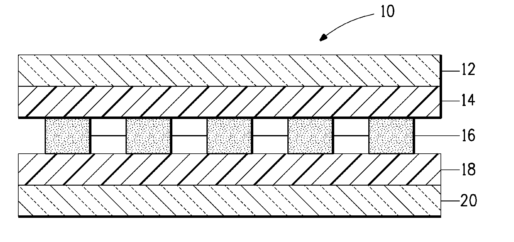
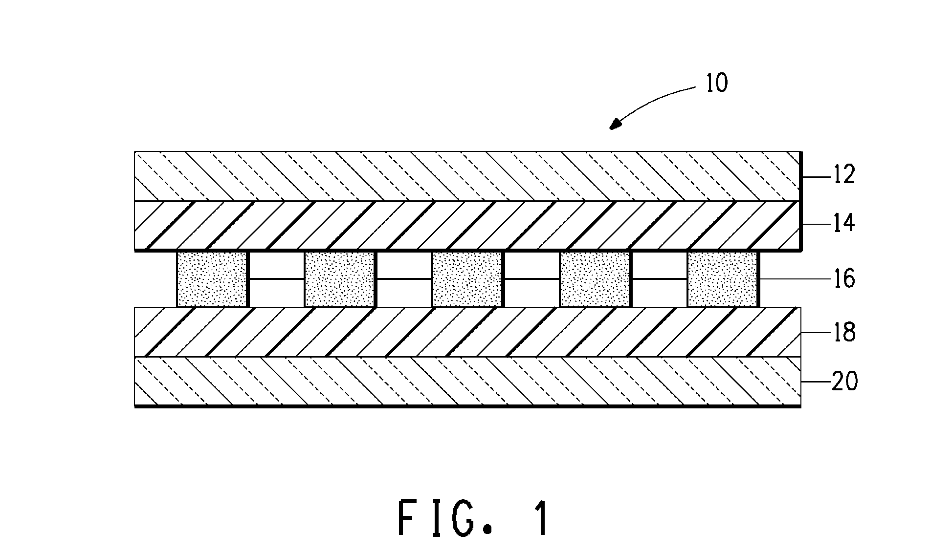
Image

Examples
example 1
[0069]A laminate sample was made by laminating an ethylene vinyl acetate (EVA) clear sheet between the CSPE sample slab no. 1 described in Table 1 above and a sheet of clear low-iron glass. The glass was ⅛ inch thick, approximately 4 inches long and approximately 4 inch wide. The CSPE test slab was a single layer with a 25 mil thickness and cut to approximately 4 inches long and approximately 4 inch wide. The EVA clear sheet from Bixby International Co., Newburyport, Mass. was 18 mil thick and was cut to 4 inches long and approximately 4 inch wide.
[0070]The lamination was accomplished by preparing a layered structure of the glass sheet followed by the sheet of clear EVA, followed by the CSPE test slab no. 1. The layered structure was placed into a lamination press having a platen heated to about 120° C. The layered structure was allowed to rest on the platen for about 6 minutes to preheat the layered structure under vacuum. The lamination press was activated and the layered structur...
example 2
[0074]A laminate sample was made by the same process as in Example 1 under the same process conditions, except that the CSPE sample slab no. 1 described in Table 1 was replaced with the CSPE / hot melt adhesive sample slab no. 2 described in Table 1 above.
[0075]The laminate sample was subjected to the damp heat exposure test described above for 1000 hours and then tested for peel strength. The sample did not undergo significant degradation. During peel strength testing, there was no failure in the bond between the CSPE / hot melt adhesive sample slab and the EVA film. Rather, the EVA film stretched before there was any failure in the bond between the CSPE / hot melt adhesive sample slab and the EVA film.
[0076]Another sample of the CSPE / hot melt adhesive slab no. 2 by itself was tested for dielectric breakdown using above described method. The average breakdown voltage was 14 KV.
[0077]Another sample of the CSPE / hot melt adhesive slab no. 2 by itself was tested according to the cut through ...
example 3
[0078]A laminate sample was made by the same process as in Example 1 under the same process conditions, except that the CSPE sample slab no. 1 described in Table 1 was replaced with the CSPE / glycerol ester hydrogenated rosin tackifier sample slab no. 3 described in Table 1 above.
[0079]The laminate sample made in such manner was subjected to the damp heat exposure test as described herein above for 1000 hours and then tested for peel strength. During peel strength testing, there was no failure in the bond between the CSPE / rosin tackifier sample slab and the EVA film. Rather, the EVA film stretched before there was any failure in the bond between the CSPE / rosin tackifier sample slab and the EVA film.
[0080]Another sample of the CSPE / rosin tackifier slab no. 3 by itself was tested for dielectric breakdown using above described method. The average breakdown voltage was 15.1 KV.
[0081]Another sample of the CSPE / rosin tackifier slab no. 3 by itself was tested according to the cut through te...
PUM
 Abstract
Description
Claims
Application Information