Sealed body, method for manufacturing sealed body, light-emitting device, and method for manufacturing light-emitting device

a technology of sealing body and sealing plate, which is applied in the direction of thermoelectric devices, transportation and packaging, other domestic articles, etc., can solve the problems of large size of the apparatus, large influence on productivity, and long time to reach the desired baking temperature, etc., and achieve high productivity and high reliability. , the effect of high-quality sealing method

Inactive Publication Date: 2012-12-20
SEMICON ENERGY LAB CO LTD
View PDF5 Cites 53 Cited by
  • Summary
  • Abstract
  • Description
  • Claims
  • Application Information

AI Technical Summary

Benefits of technology

[0036]According to an embodiment of the present invention, a highly productive method for sealing substrates with glass frit can be provided. Further, a method for sealing substrates with glass frit, which can be used for a substrate provided with a mat

Problems solved by technology

However, such a heating apparatus is large in size and it takes a long time to reach desired baking temperature due to heat capacity of a substrate.
Accordingly, productivity is greatly affected by a long process time in a step of baking the paste, high initial cost and running cost of the heating apparatus, and th

Method used


Image

  • Sealed body, method for manufacturing sealed body, light-emitting device, and method for manufacturing light-emitting device
  • Sealed body, method for manufacturing sealed body, light-emitting device, and method for manufacturing light-emitting device
  • Sealed body, method for manufacturing sealed body, light-emitting device, and method for manufacturing light-emitting device

Examples


embodiment 1

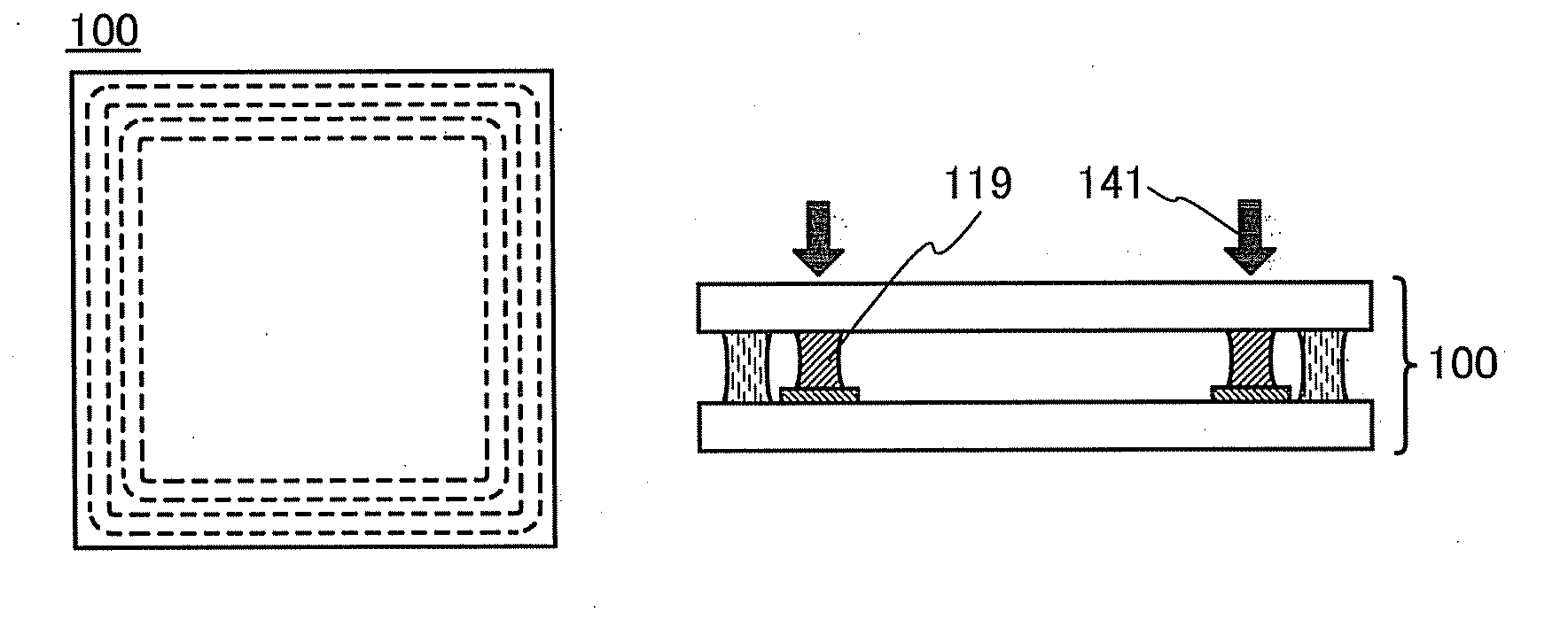
[0048]In this embodiment, a method for manufacturing a sealed body, according to an embodiment of the present invention, will be described with reference to FIGS. 1A to 1D, FIGS. 2A and 2B, and FIGS. 3A to 3E.

example 1

MANUFACTURING METHOD EXAMPLE 1

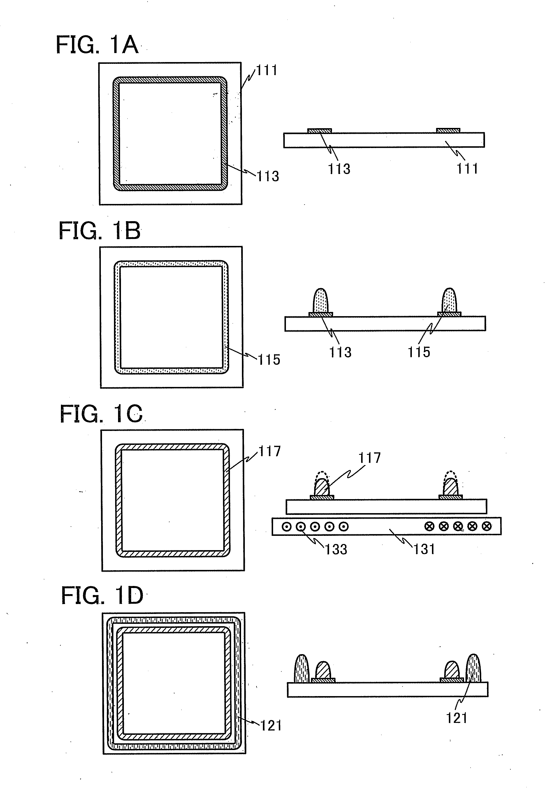
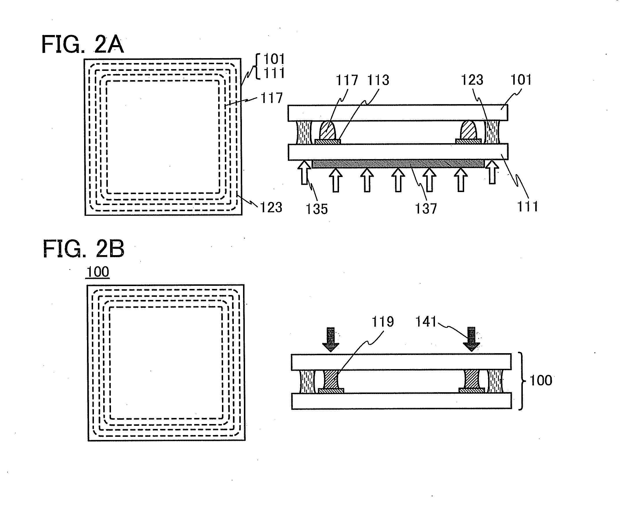
[0049]FIGS. 1A to 1D and FIGS. 2A and 2B illustrate a method for manufacturing a sealed body described in this manufacturing method example. In each of FIGS. 1A to 1D and FIGS. 2A and 2B, a schematic top view and a corresponding schematic cross-sectional view are illustrated.

[0050]First, a heat generation layer 113 is formed over a first substrate 111 (see FIG. 1A). The heat generation layer 113 includes a conductive material which can generate heat in later induction heating treatment. The heat generation layer 113 includes a material which generates heat enough to heat a frit paste 115 formed over the heat generation layer 113 so that a binder in the frit paste 115 is removed and a frit material in the frit paste 115 is melted. Note that a material which can withstand at least temperature at which the binder contained in the frit paste 115 is removed is used for the heat generation layer 113.

[0051]As a material which can generate heat by induction hea...

example 2

MANUFACTURING METHOD EXAMPLE 2

[0079]When a conductive material is included in a frit paste, the frit paste itself can be baked by an induction heating method without the heat generation layer 113. A method for manufacturing a sealed body with the use of a frit paste including a conductive material will be described below with reference to FIGS. 3A to 3E. Note that description of the portions described in Manufacturing Method Example 1 is omitted or is simply given.

[0080]FIGS. 3A to 3E illustrate a method for manufacturing a sealed body described in this manufacturing method example. Note that each of FIGS. 3A to 3E illustrates a schematic cross-sectional view of a step.

[0081]First, a frit paste 155 is formed over the first substrate 111 (see FIG. 3A).

[0082]The frit paste 115 to which a conductive material is added is used as the frit paste 155. Any of the materials which can be used for the heat generation layer 113 can be used as the conductive material. The conductive material is ...


PUM

PropertyMeasurementUnit
Diameteraaaaaaaaaa
Diameteraaaaaaaaaa
Shapeaaaaaaaaaa

Abstract

A highly productive method for sealing substrates with the use of glass frit is provided. A method for sealing substrates with the use of glass frit, which can be used for a substrate provided with a material having low heat resistance, is provided. A highly airtight sealed body which is manufactured by such a method is provided. A light-emitting device having high productivity and high reliability and a manufacturing method thereof are provided. A heat generation layer containing a conductive material which generates heat by induction heating is formed to overlap with a region where a paste including a frit material and a binder is applied. Alternatively, a conductive material which generates heat by induction heating is added to the paste itself. The paste is locally heated by induction heating to remove the binder included in the paste.

Description

BACKGROUND OF THE INVENTION[0001]1. Field of the Invention[0002]The present invention relates to a sealed body including two substrates and a method for manufacturing the sealed body. Further, the present invention relates to a light-emitting device including an organic EL element and a method for manufacturing the light-emitting device.[0003]2. Description of the Related Art[0004]A technique in which a highly airtight sealed body is formed in such a manner that two substrates are bonded to each other by glass frit (also referred to as frit glass) including low-melting glass is known. In a technique disclosed in Patent Document 1, a paste containing a binder and a frit material including low-melting glass is applied to a glass substrate along an edge of the glass substrate, the binder is removed and the frit material is melted to form glass frit by baking of the paste, the glass frit is irradiated with laser light with the substrate overlapping with a counter substrate, and the glas...

Claims


Application Information

Patent Timeline
IPC IPC(8): H01L51/52B32B7/04B32B37/12
CPCB32B37/06Y10T428/24744B32B2309/105B32B2309/60B32B2309/65B32B2310/0812B32B2310/0843B32B2457/20B32B2457/206H01L51/5246H01L27/156H01L33/483H01L33/56H01L33/58B32B2309/02H10K50/8426H05B33/04H10K71/00
Inventor SHIMOMURA, AKIHISA
Owner SEMICON ENERGY LAB CO LTD
Why Eureka
Try Eureka