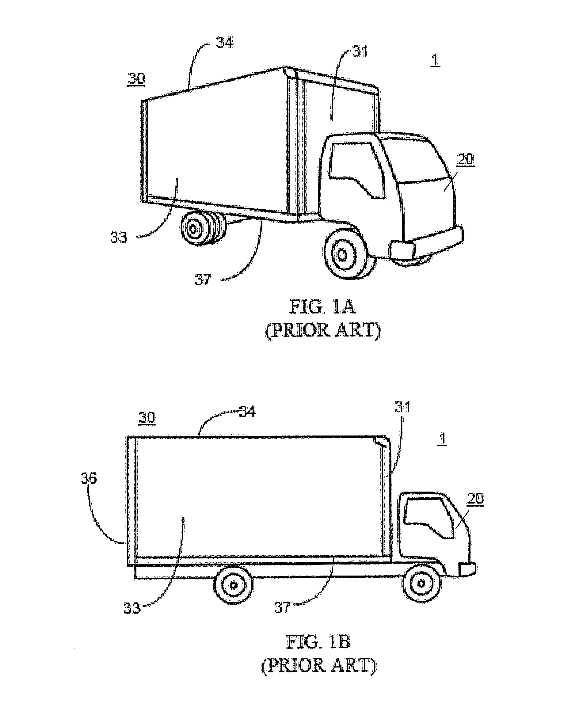
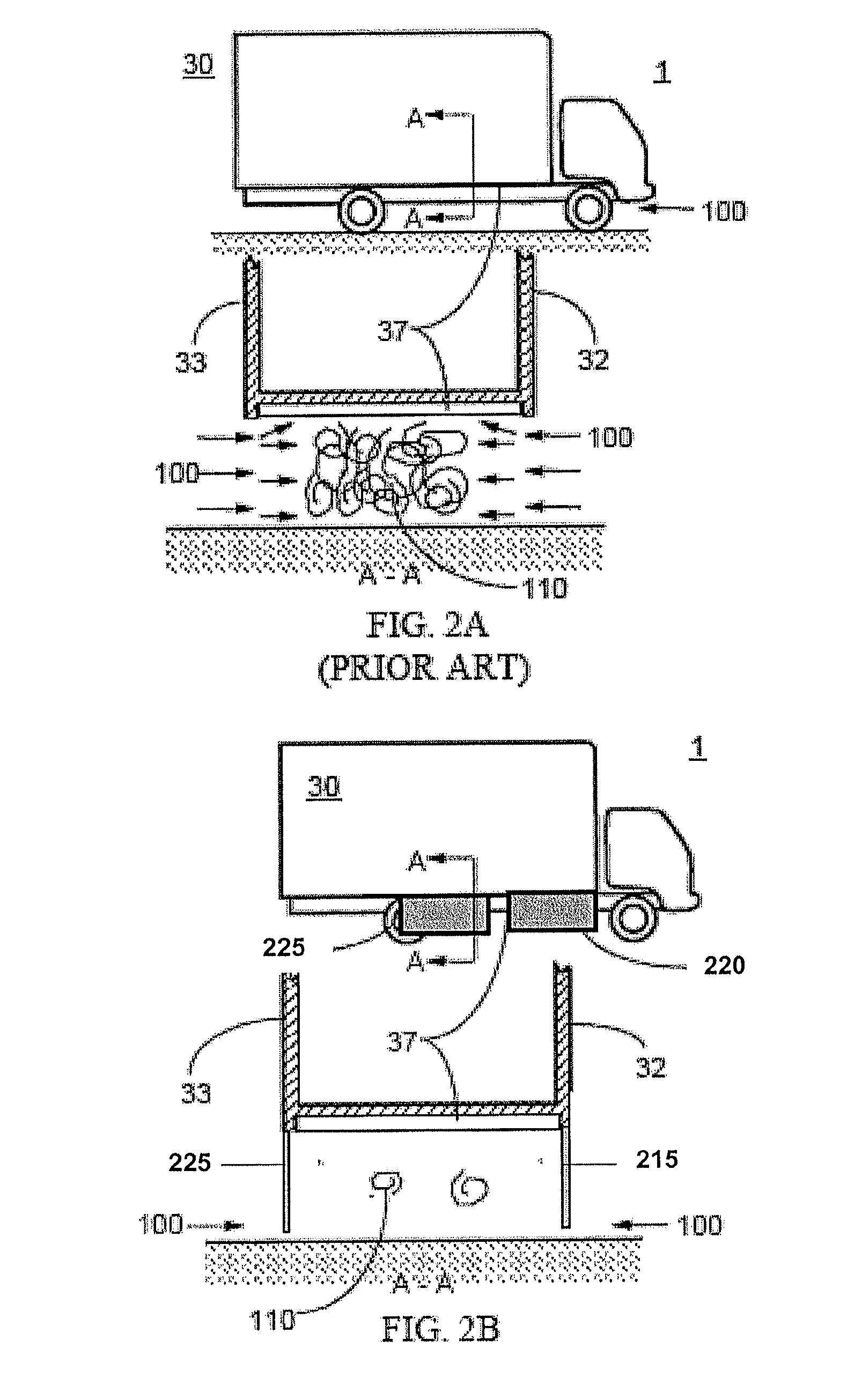
[0011]One functional aspect of the device is to prohibit flow from entering the undercarriage region and interacting with the complex geometry of the undercarriage and wheel
assembly by creating two similar structures that attach to the underside or the sides of the vehicle. The two similar panel systems of the present apparatus are light-weight aerodynamic fairings that attach to the structure of a ground vehicle that may be a single unit, un-articulated, ground vehicle or a component of an articulated ground vehicle such as a trailer. The left and right side panel systems of the apparatus may attach to the vehicle near the outside edges of the vehicle or vehicle component. The left and right side panel systems are two similar structures that
mount to the right and left side of a vehicle and are of minimum vertical extent where each left and each right side panel
system include a forward portion and a rear portion that attach to the vehicle. The first and second aft panel system can be positioned in a manner to cover the outer facing surface of the aft most tire and wheel system of a vehicle and the first and second forward panel system is substantially forward of and separated from the respective first and second aft potion of each panel system. Alternatively, the first and second aft panel systems can be positioned such that the rear edges of the first and second aft panel system are located forward of, and in close proximity to, the forward portion of the aft-most tire and wheel systems such that the aft panel systems do not obstruct lateral access to tire and wheel systems. Each aft panel system may extend vertically downward as close as practical to the ground based upon operational and maintenance criteria. Each panel system is located longitudinally between the aft end of the vehicle or vehicle component and the vehicle forward wheel
assembly. Each structure is variable in length and is capable of covering a variable longitudinal distance between the vehicle aft end and the vehicle forward wheel assembly.
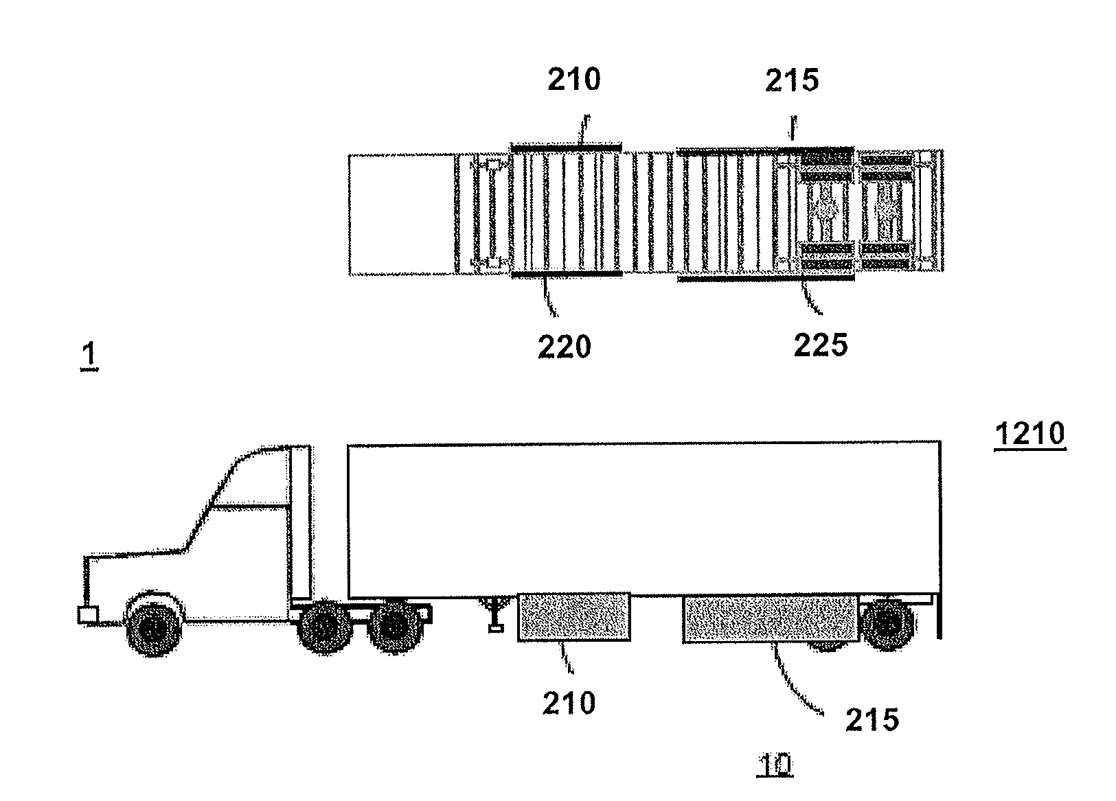
[0012]The flow blocking performance of each of the two panel systems is enhanced through the effective use of ground effect interference. Each of the two panel systems accomplishes the flow control and drag reduction goals with a vertically orientated surface that has an aft panel system and a forward panel system. The forward and aft panel systems of each structure may be of similar or varying longitudinal and vertical length.
[0014]The forward panel system of each structure is designed to
control flow from entering the undercarriage region by redirecting the flow over aerodynamically shaped surfaces of the forward panel system and away from the undercarriage region. The forward panel system may also be designed to redirect residual flow inboard over aerodynamically contoured surfaces that will control the flow to minimize drag. The longitudinal position of the forward panel system is critical to maximizing the flow control benefit while minimizing the aerodynamic drag force acting on the forward panel system. One or more of the aft panel systems of each panel system is designed to block flow from impinging on the aft wheel system,
bogie and undercarriage structure. The flow control strategy allows the device to block a significantly greater mass of flow from entering the undercarriage region compared to a typical single panel fairing of equal weight and surface area.
[0015]In certain embodiments, an apparatus for reducing the aerodynamic drag of a vehicle trailer body is provided. The trailer body has a bottom defining an undercarriage region, a left side defining a left side surface, a right side defining a right side surface, the trailer further including a right aft-most wheel assembly, a left aft-most wheel assembly, and a sliding
bogie configured to permit the right and left wheel assemblies to be slid longitudinally with respect to the trailer body. The trailer body is configured for transport over a
road surface. The apparatus includes a substantially rectangular left forward panel having a width (LFPH) and a length (LFPL), a substantially rectangular left aft panel having a width (LAPH) and a length (LAPL), a substantially rectangular right forward panel having a width (RFPH) and a length (RFPL), and a substantially rectangular right aft panel having a width (RAPH) and a length (RAPL). The left aft panel and left forward panel are configured to attach to a lower left portion of the trailer such that they extend downward from the undercarriage region. The left forward panel is positioned forward of the left aft panel. The left aft panel and the left forward panel are approximately parallel to the left side surface of the trailer. The right aft panel and right forward panel are configured to attach to a lower right portion of the trailer such that they extend downward from the undercarriage region. The right forward panel is positioned forward of the right aft panel. The right aft panel and the right forward panel are approximately parallel to the right side surface of the trailer. The width of each of the panels is less than or equal to about 95% of a distance between the trailer bottom surface and the
road surface. The left aft panel and the right aft panel are secured to the sliding
bogie such that they move longitudinally with the sliding bogie. The left aft panel is positioned longitudinally such that a forward edge of the left aft panel is located forward of the left wheel assembly. The right aft panel is positioned longitudinally such that a forward edge of the right aft panel is located forward of the right wheel assembly. The left forward panel and the left aft panel are separated longitudinally so as to define a first gap having a length (LGL) that is greater than about 6 inches. The right forward panel and the right aft panel being separated longitudinally so as to define a second gap having a length (RGL) that is greater than about 6 inches. The apparatus is configured to reduce aerodynamic drag on the trailer by reducing
airflow entering the undercarriage region from the sides of the trailer when the trailer is moving in a forward direction over the
road surface.
[0020]In certain embodiments, each of the panels may be configured to attach to the bottom of the trailer. In other embodiments, the panels may be configured to attach to the trailer's side surfaces. The apparatus may include a plurality of angled brackets configured to attach to the bottom of the trailer and secure a corresponding panel in place. In certain embodiments, an apparatus for reducing the aerodynamic drag of a ground vehicle is provided. The ground vehicle has a body including a bottom defining an undercarriage region, a left side defining a left side surface, a right side defining a right side surface. The vehicle further includes a right aft-most wheel assembly and a left aft-most wheel assembly. The vehicle is configured for transport over a road surface. The apparatus includes a substantially rectangular left forward panel having a width (LFPH) and a length (LFPL), a substantially rectangular left aft panel having a width (LAPH) and a length (LAPL), a substantially rectangular right forward panel having a width (RFPH) and a length (RFPL), a substantially rectangular right aft panel having a width (RAPH) and a length (RAPH). The left aft panel and left forward panel are configured to attach to a lower left portion of the vehicle body and extend downward from the undercarriage region. The left forward panel is positioned forward of the left aft panel. The left aft panel and the left forward panel are approximately parallel to the left side surface of the vehicle body. The right aft panel and right forward panel are configured to attach to a lower right portion of the vehicle and extend downward from the undercarriage region. The right forward panel is positioned forward of the right aft panel. The right aft panel and the right forward panel are approximately parallel to the right side surface of the vehicle body. The width of each of the panels is less than or equal to about 95% of a distance between the vehicle bottom surface and the road surface. The left aft panel is positioned longitudinally such that a forward edge of the left aft panel is located forward of the left wheel assembly. The right aft panel is positioned longitudinally such that a forward edge of the right aft panel is located forward of the right wheel assembly. The left forward panel and the left aft panel are longitudinally separated by a gap having a length (LGL) that is greater than about 6 inches. The right forward panel and the right aft panel are longitudinally separated by a gap having a length (RGL) that is greater than about 6 inches. The apparatus is configured to reduce aerodynamic drag on the vehicle by reducing
airflow entering the undercarriage region from the sides of the vehicle body when the trailer is moving in a forward direction over the road surface.

